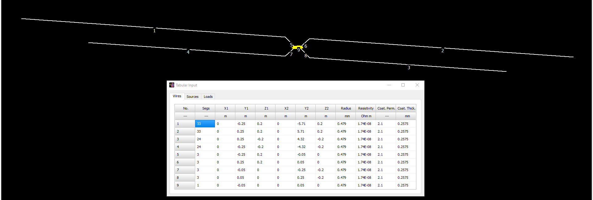
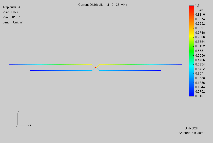
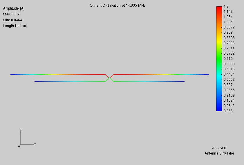
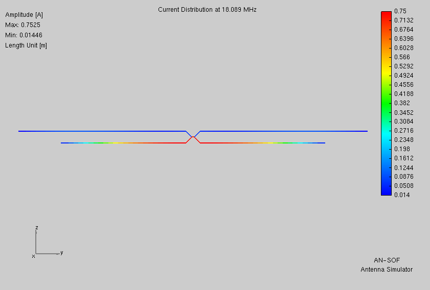
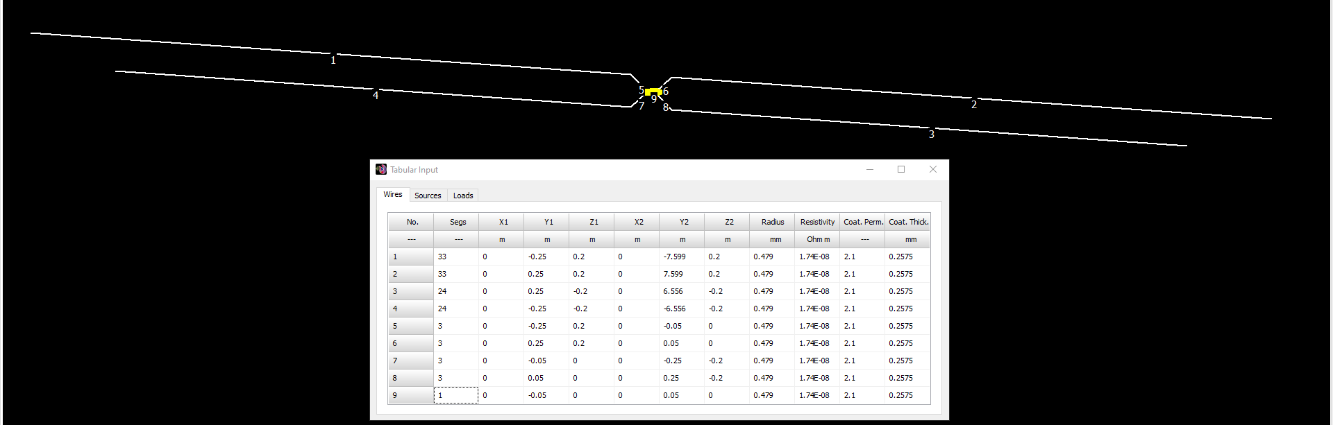
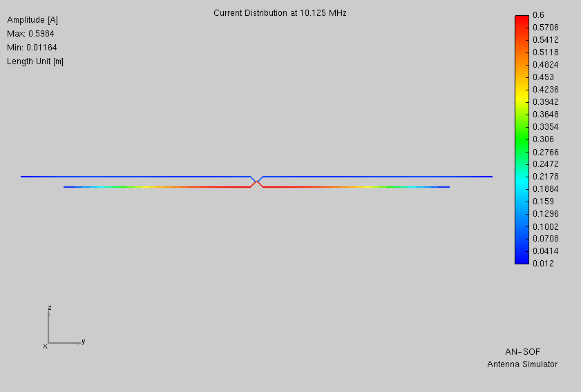
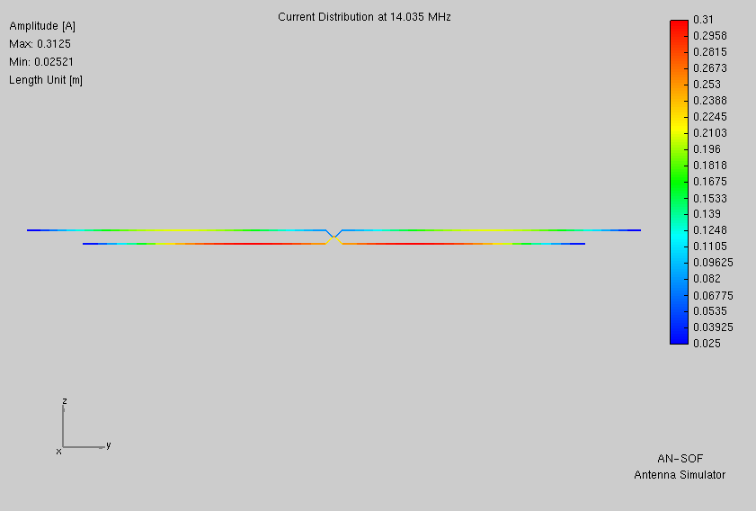
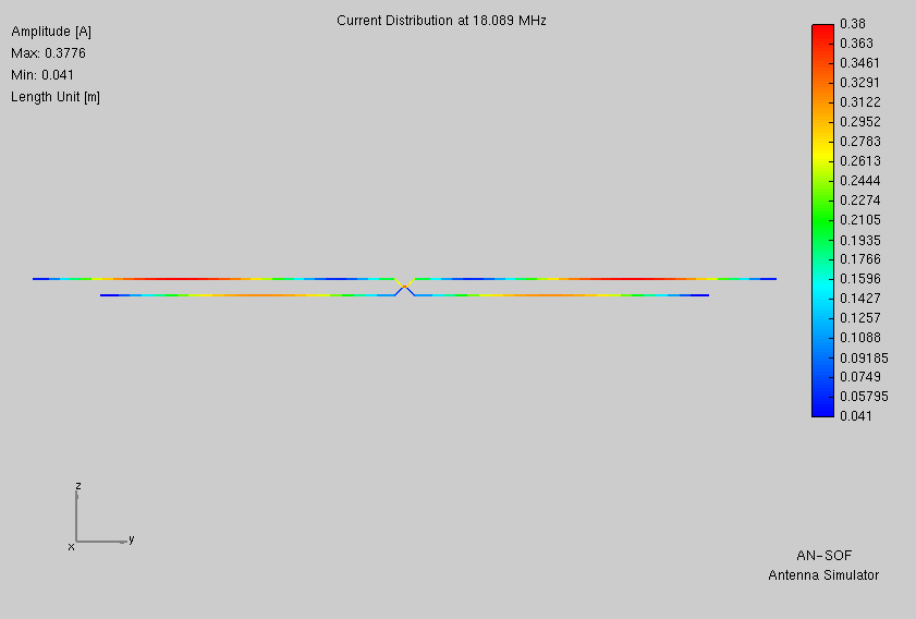
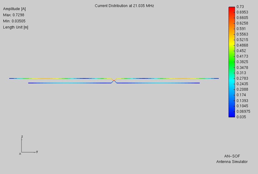
Non-resonant dual-dublets wholly compatible with auto-tuners.
A series of planned experiments
interrupted part way through
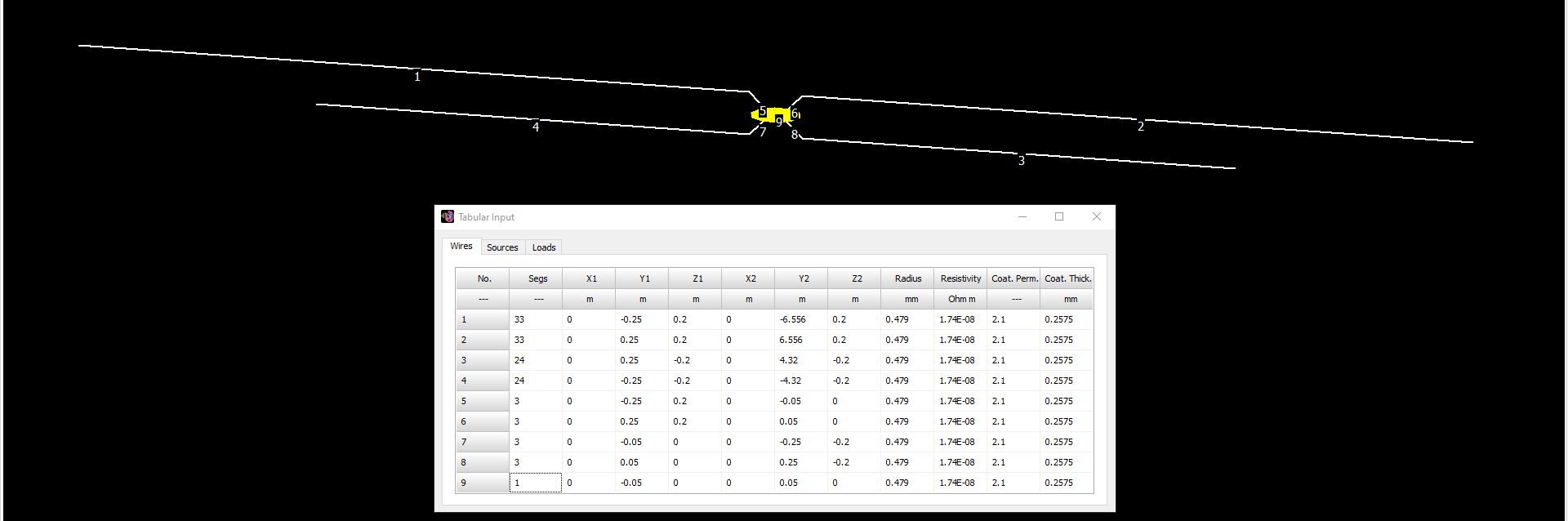
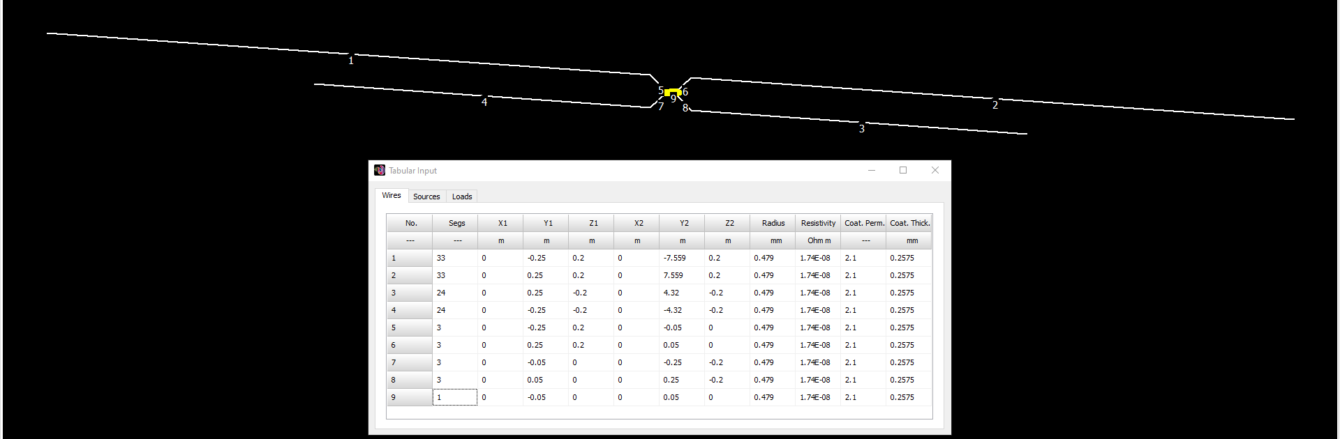
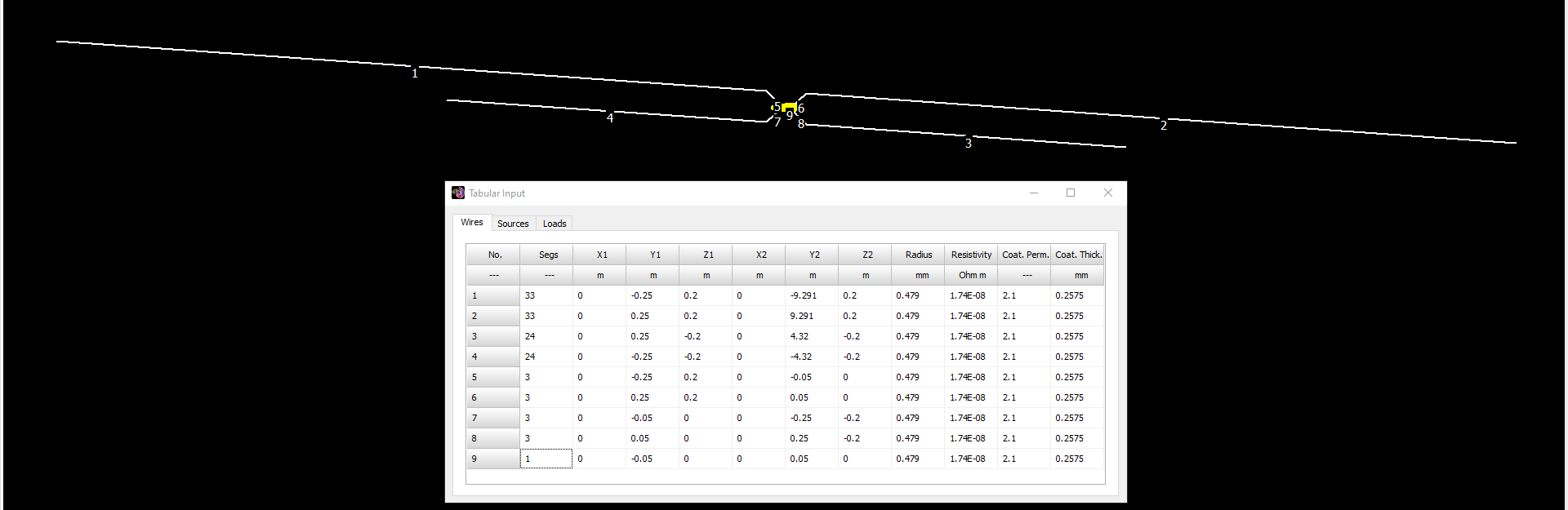
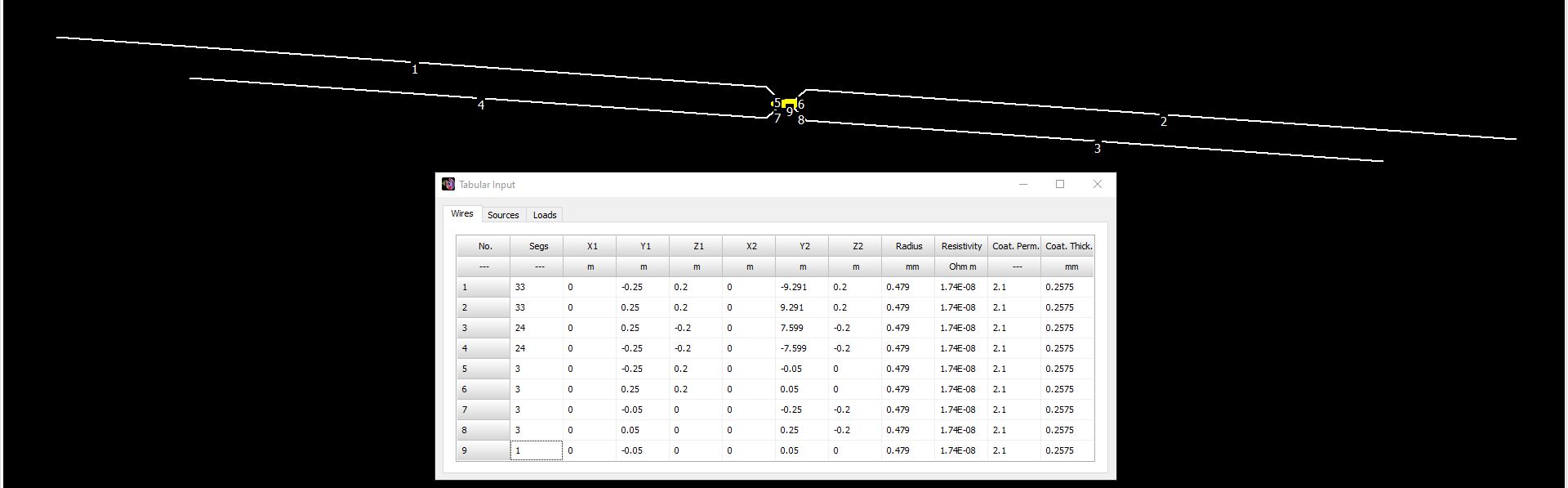
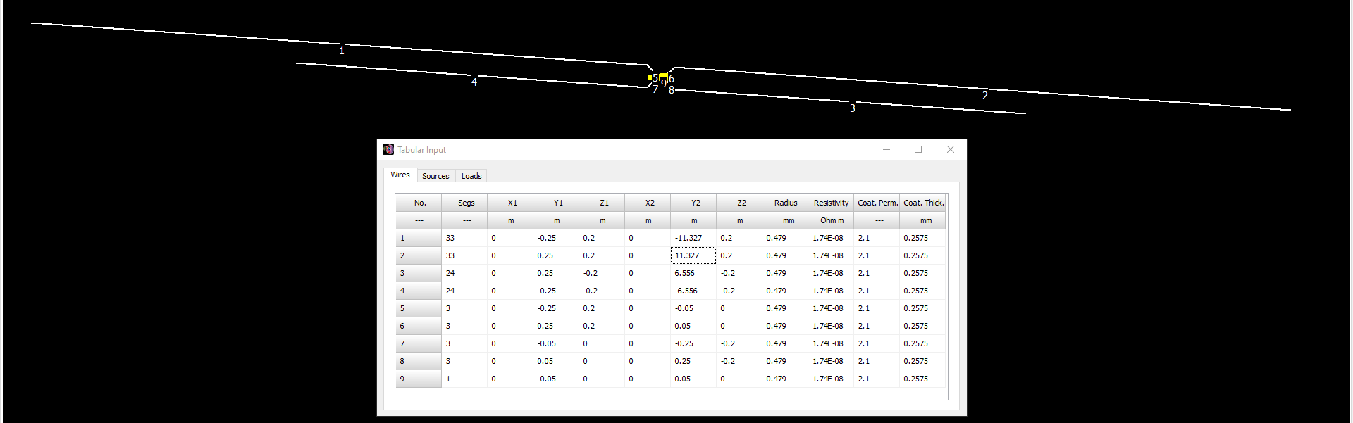
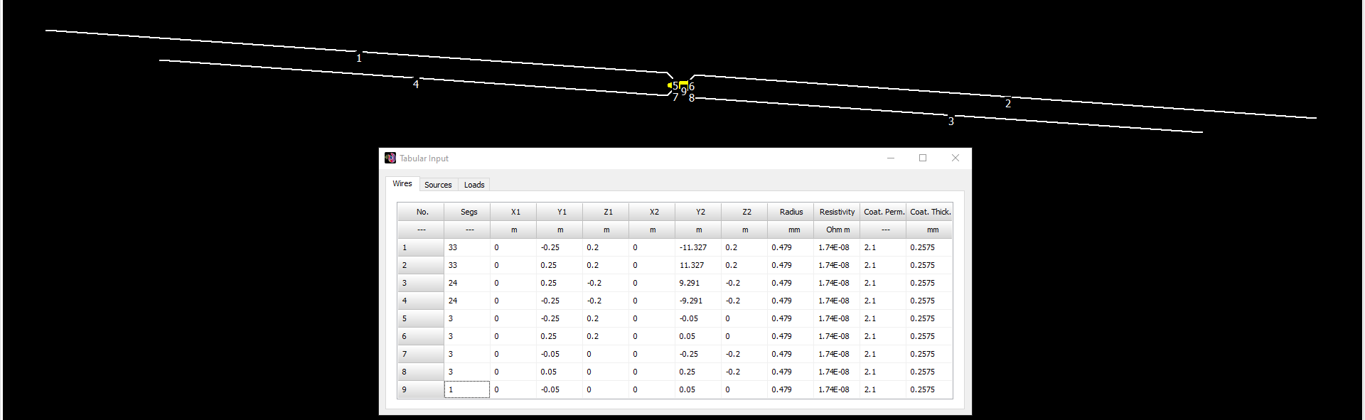
Here I explore the concept of non-resonant dual-doublet antennas: length combinations friendly to auto-tuners from 10m through 30m minimum, WARC bands included.
Many a modern HF rig has an auto-tuner built in. While great for protecting the rig, it still allows signal losses inside the coax. An auto-tuner at the far end cures that. But remote auto-tuners have limited range. And even inside a given model’s advertized range un-tunable sub-ranges often exist.
Hence my search for an antenna wholly friendly to auto-tuners without any such vexing gaps. This for portable use. Something which doesn’t exclude the WARC bands. Something efficient, and so without a lossy 5:1 balun. Something less heavy and complicated than a 6- or 7-band multi-wire or trap dipole.
What might fit such a bill? Something non-resonant most probably. Something very likely fed by nearly lossless parallel feedline, but without said feedline itself being a radiating member.
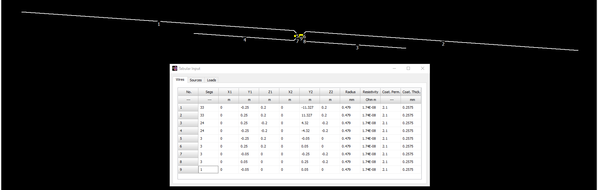
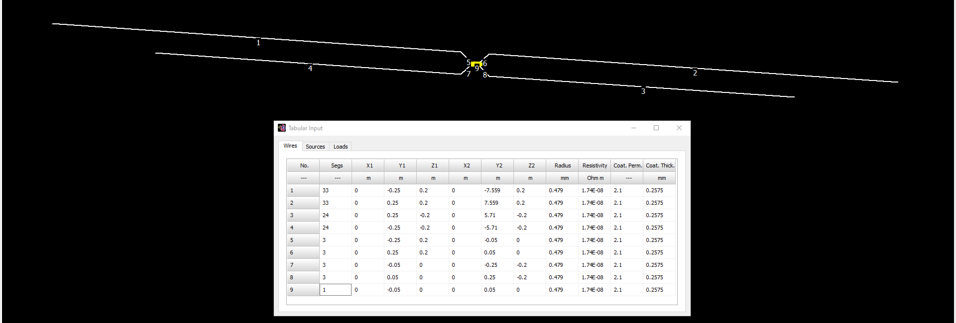
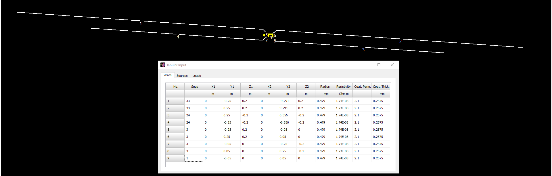
Firstly I modeled several ordinary doublets. Each employed non-resonant wire lengths. None afforded tuning solutions wholly within auto-tuner range for every band. Hence the idea to mix and match these same non-resonant wire lengths instead as pairs.
Autotuners use relays to switch discrete capacitors and toroid inductors into and out of circuit, thereby creating a low-pass L network. Which, while more efficient than a high-pass T network (manual 3-knob units) the trade-off is reduced range.
Be aware that instances will exist where an antenna’s tuning solution might require two capacitors and no inductor at all. Whereupon any auto-tuner will surely fail to obtain a match. This despite SWR (as read by meter) falling within said auto-tuner’s advertized range.
Below are presented the L and C ranges for four common auto-tuners, two built into their rigs, two external.
| μHmin | μHmax | pFmin | pFmax | |
|---|---|---|---|---|
| Mission RGO One | 0.05 | 8.42 | 10 | 2531 |
| Elecraft K3 | 0.05 | 17.34 | 12 | 2627 |
| LDG RT-100 | 0.11 | 10.17 | 10 | 1270 |
| ATU-100 | 0.05 | 8.42 | 10 | 1869 |
The antenna modeling program AN-SOF has separate tabs for Tuning and Feeder. Choosing low-pass L network as type of tuner, I note the values predicted for L and C at the top, middle, and bottom of each band. Selfishly, I focus on the CW regions only. Like so for each wire length combination.
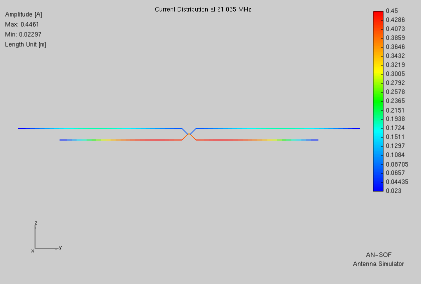
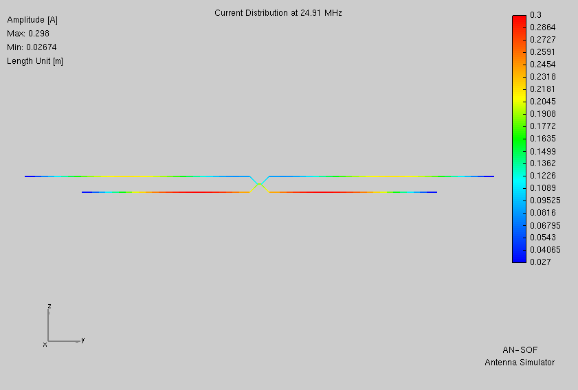
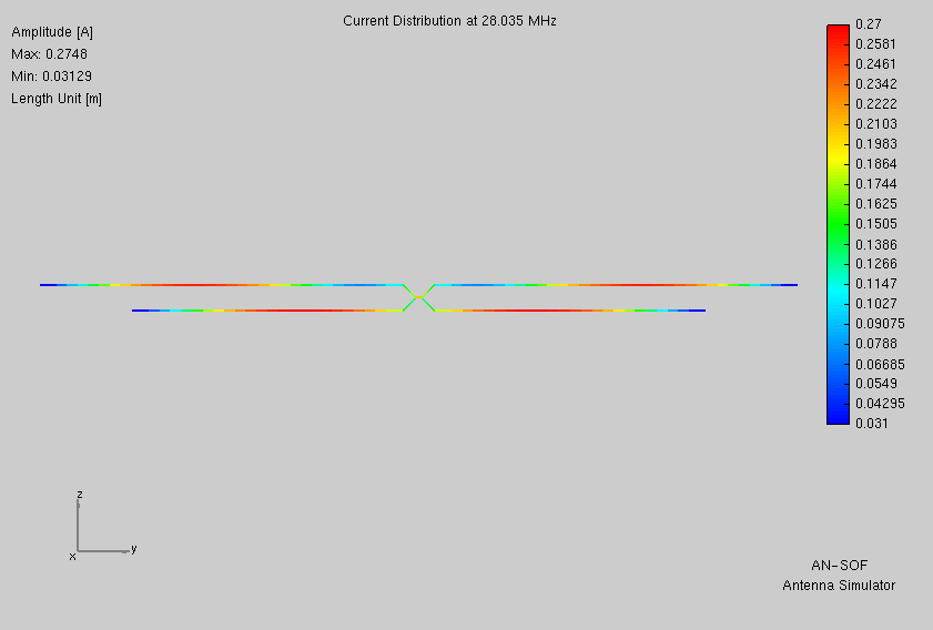
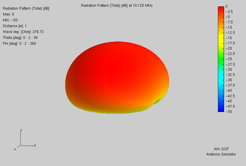
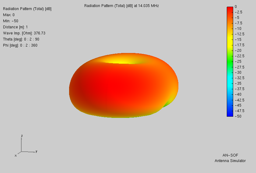
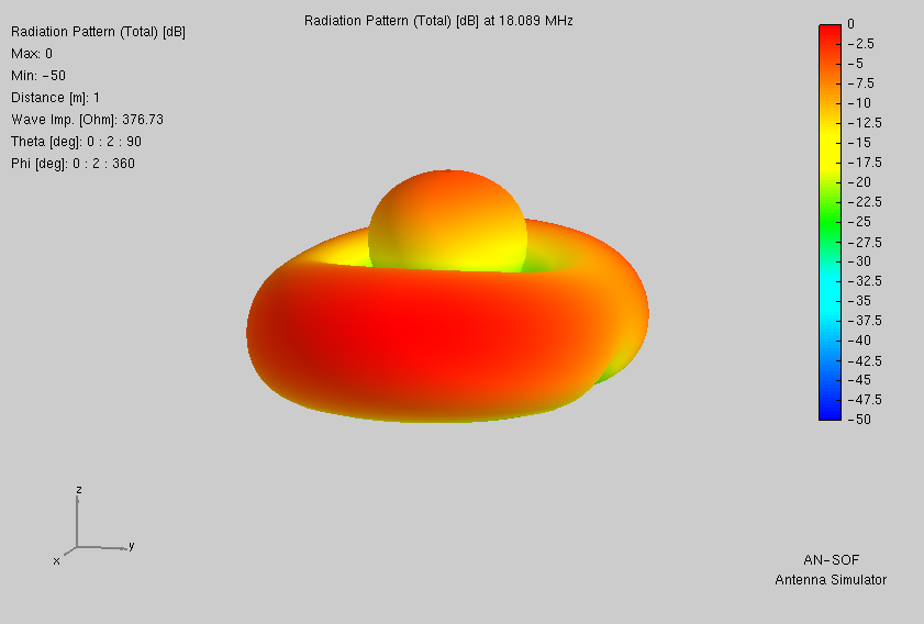
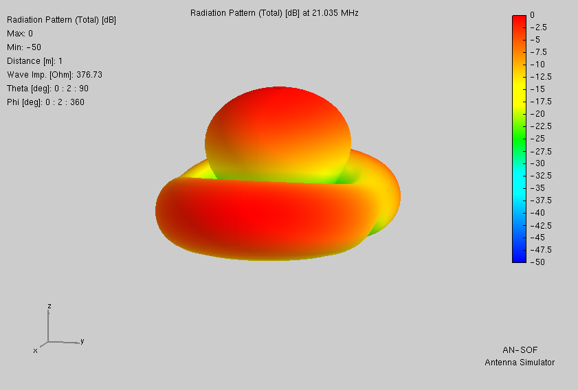
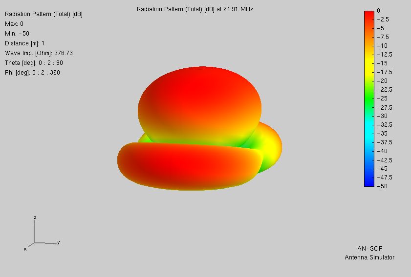
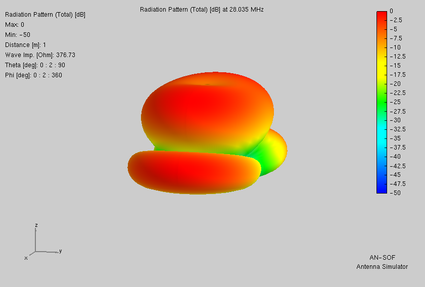
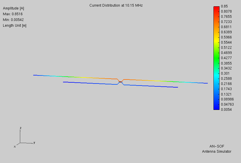
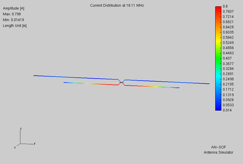
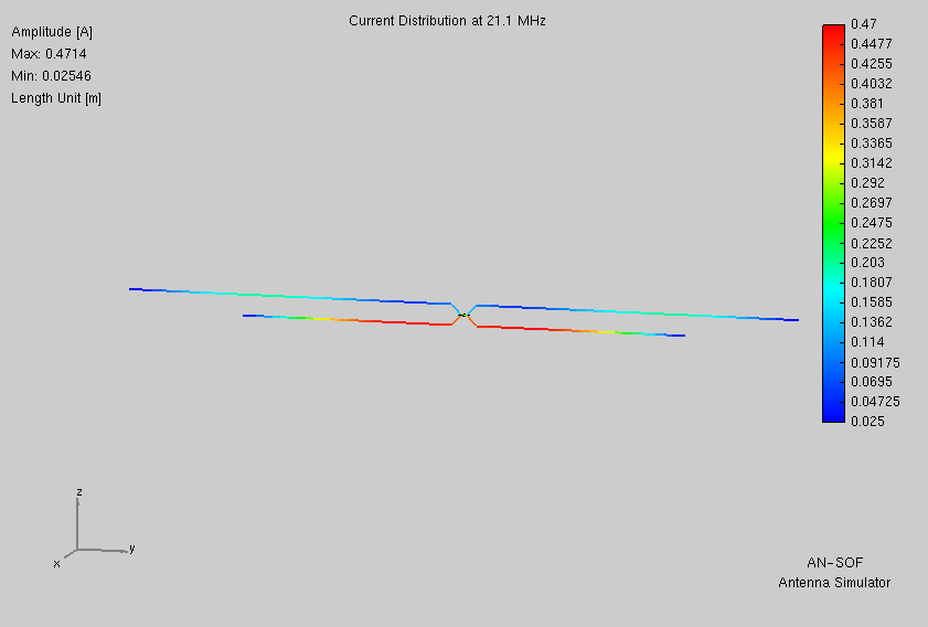
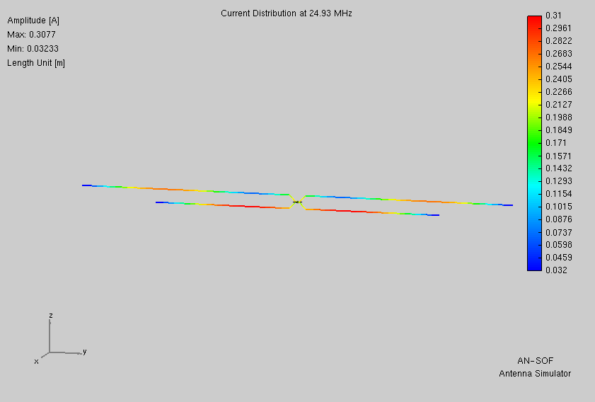
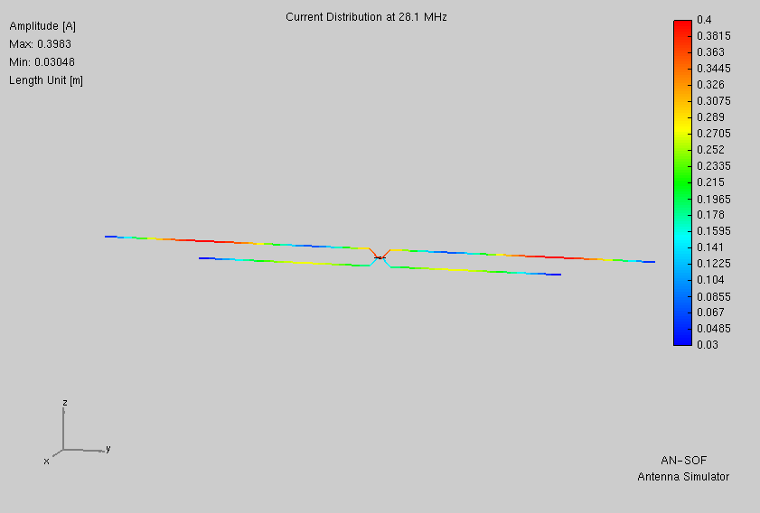
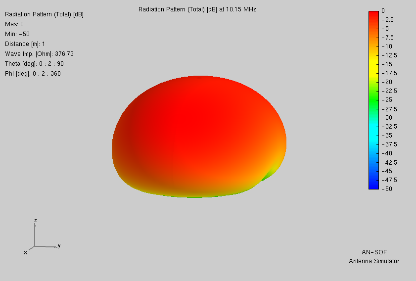
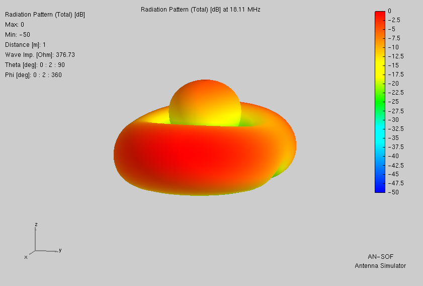
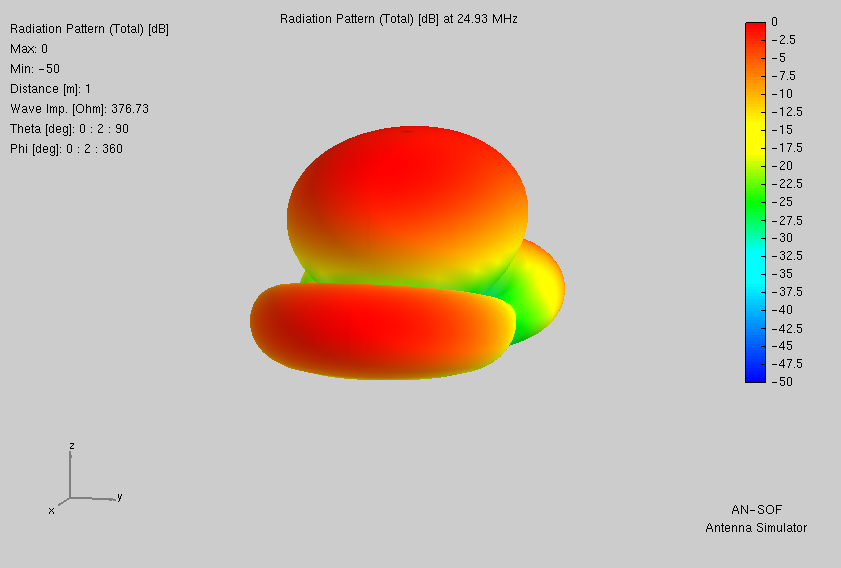
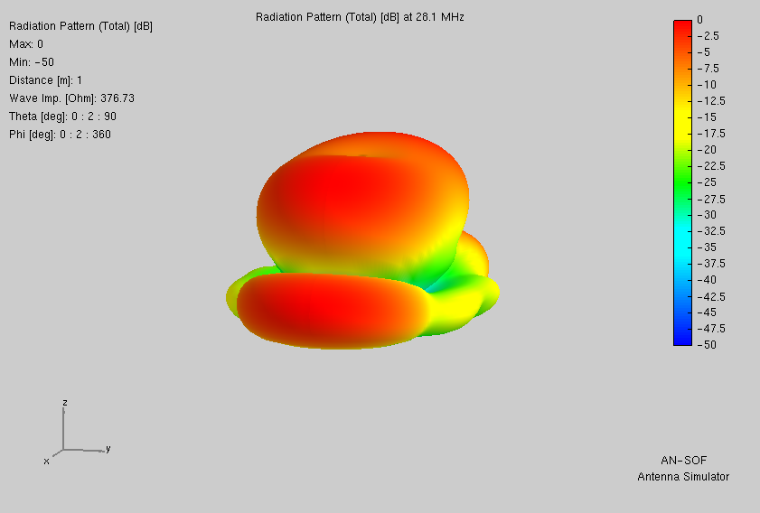
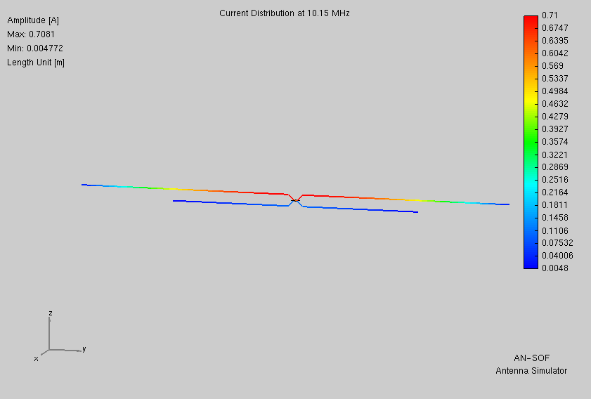
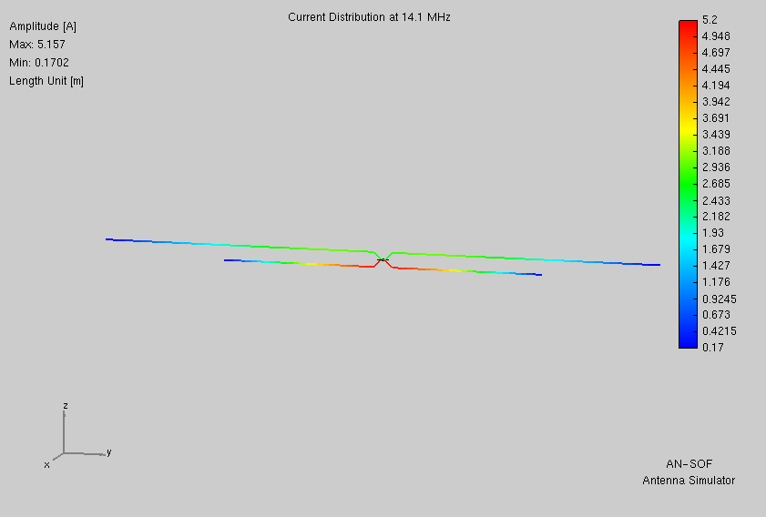
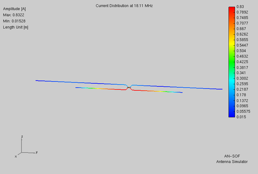
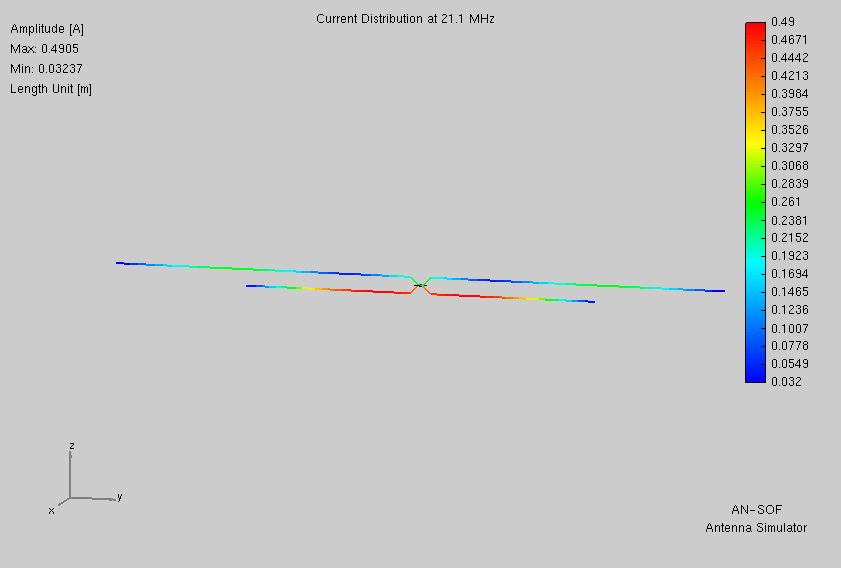
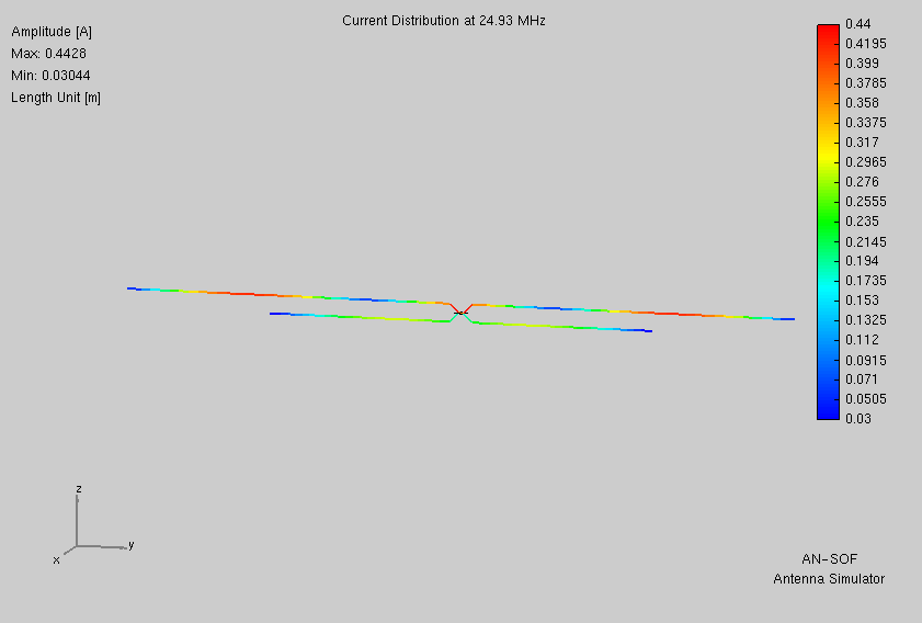
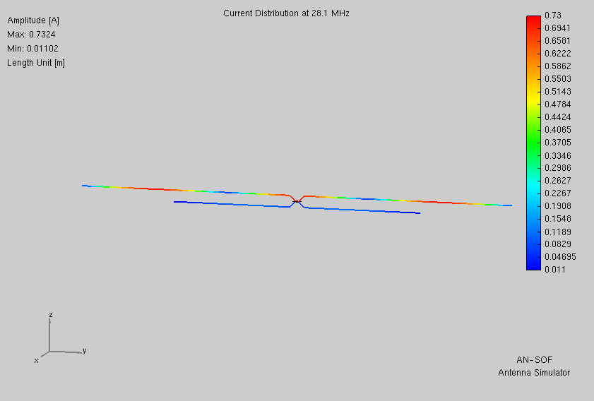
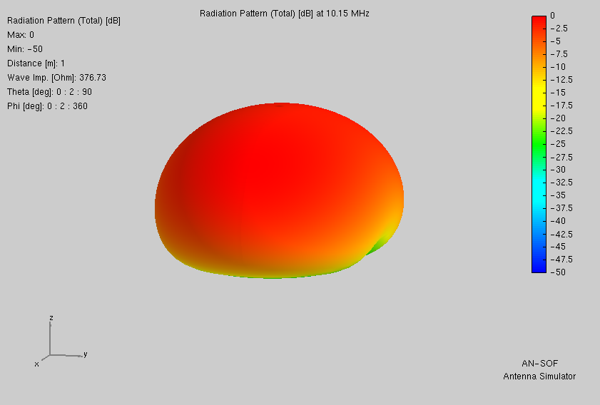
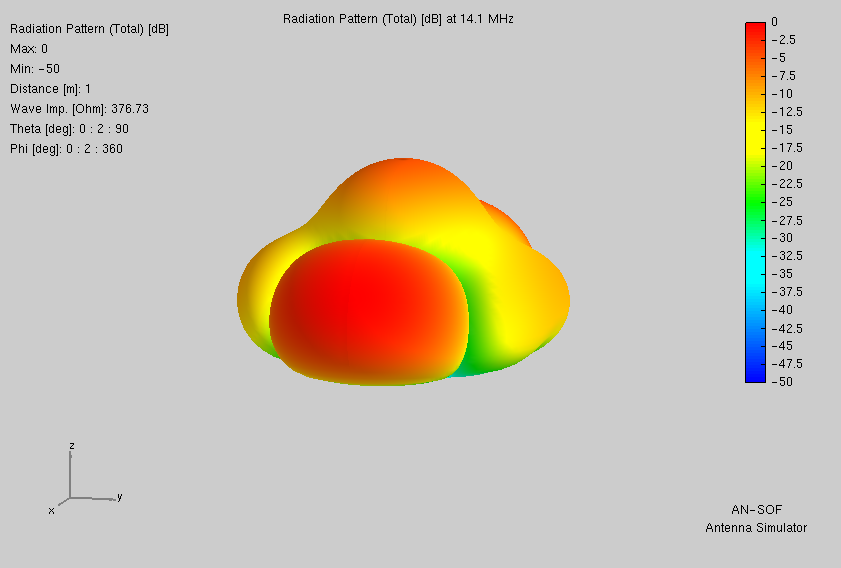
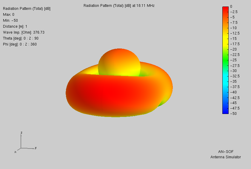
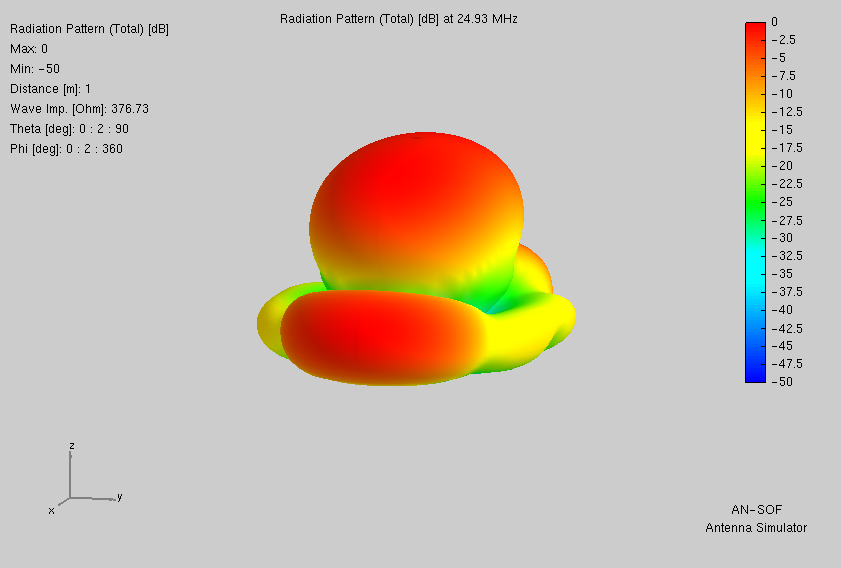
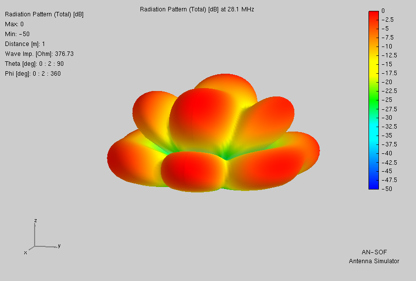
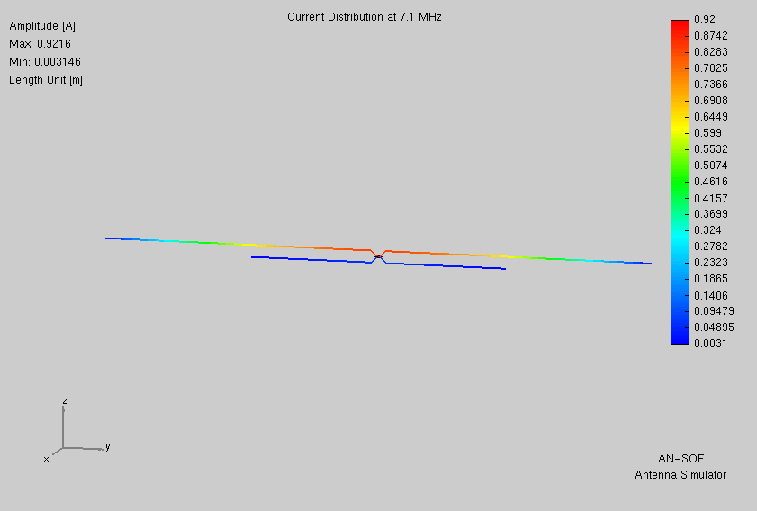
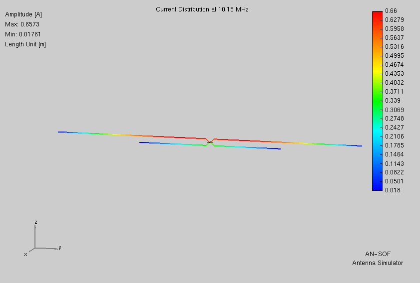
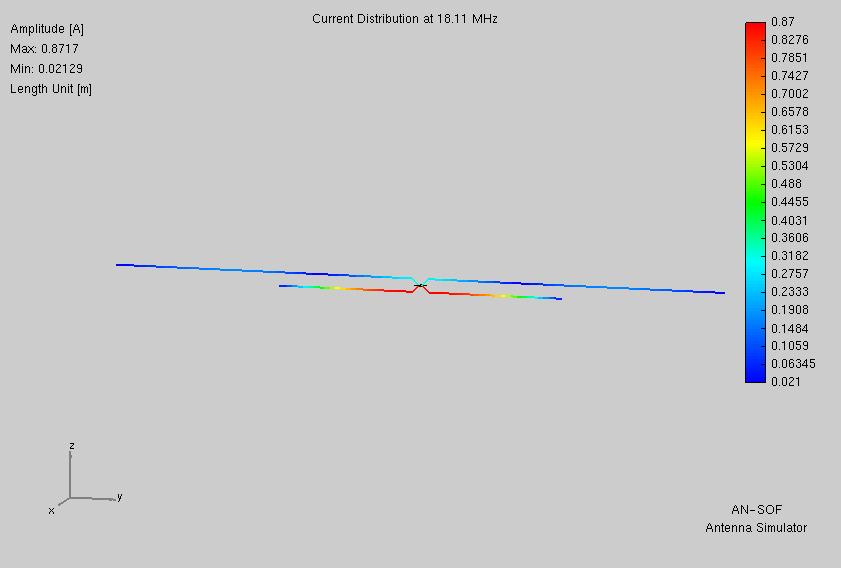
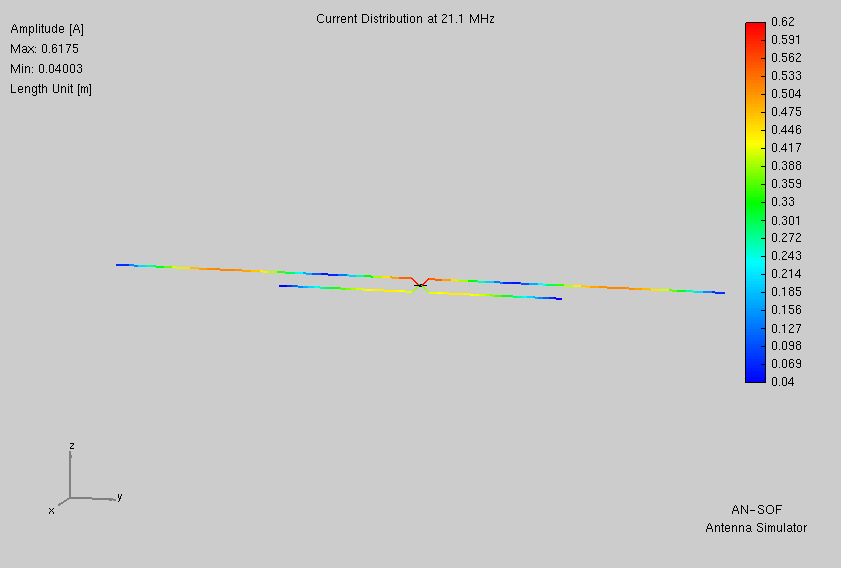
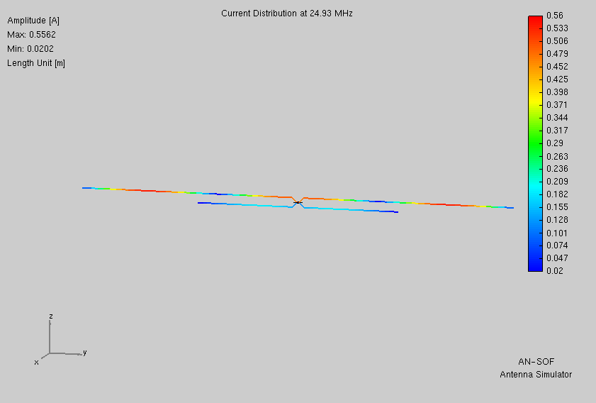
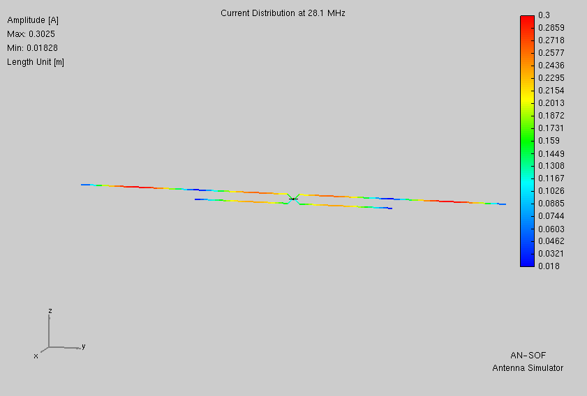
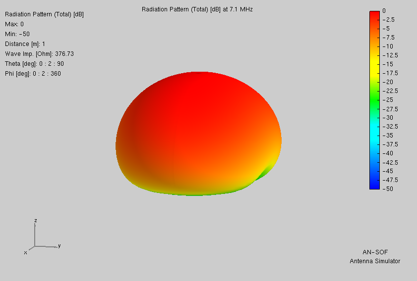
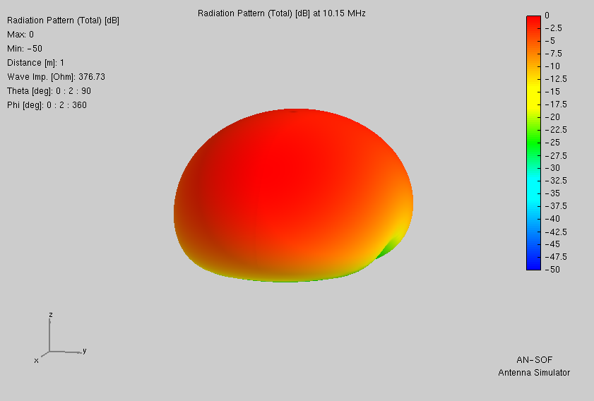
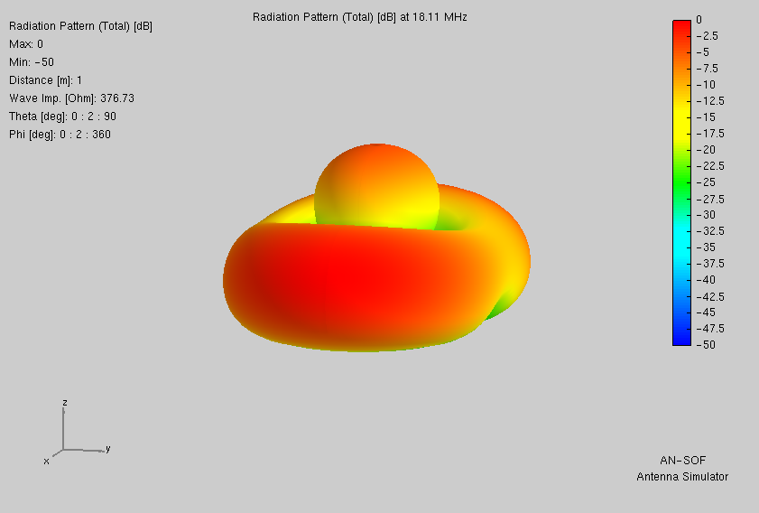
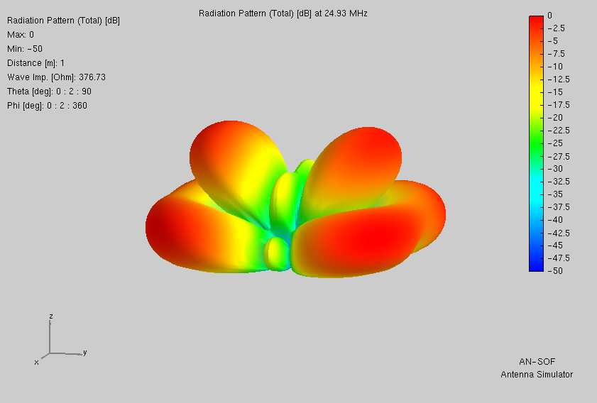
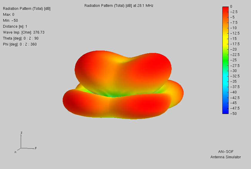
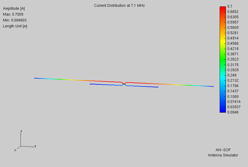
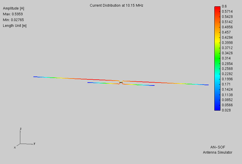
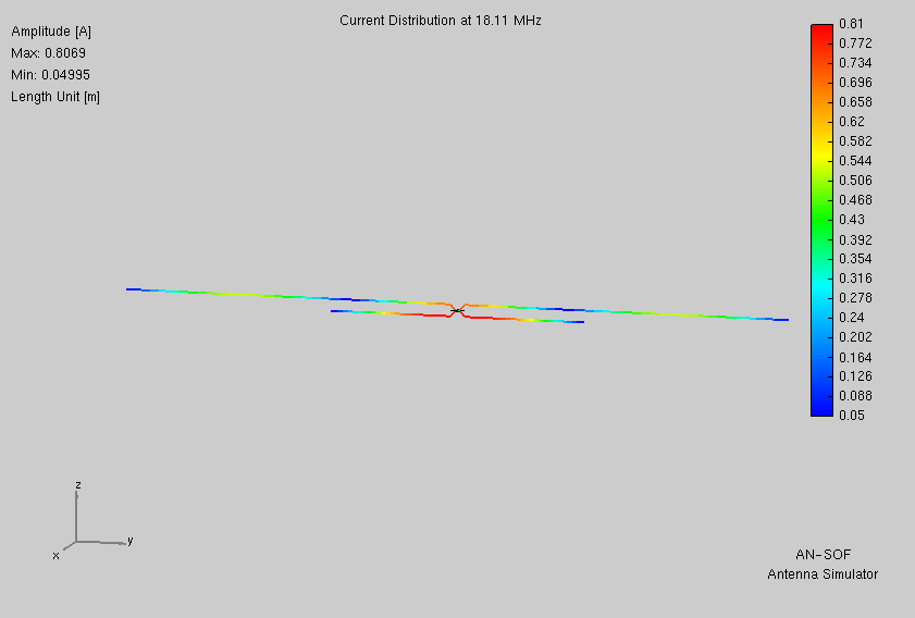
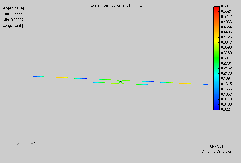
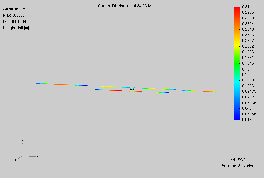
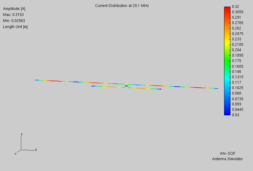
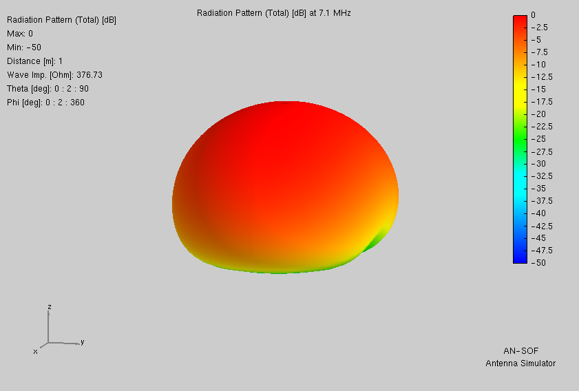
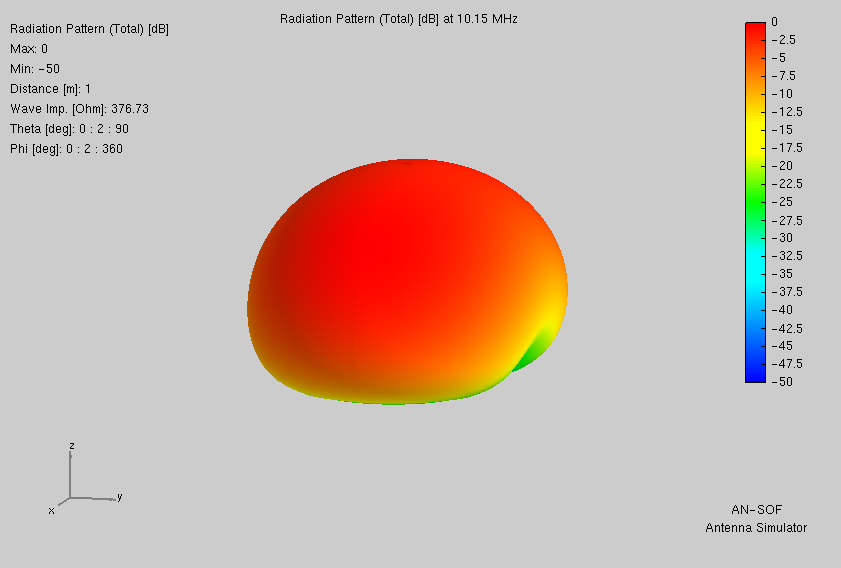
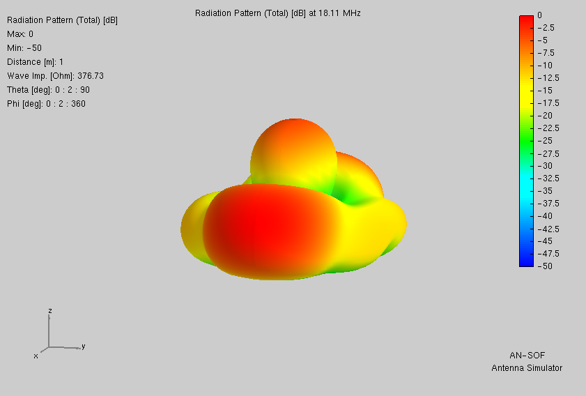
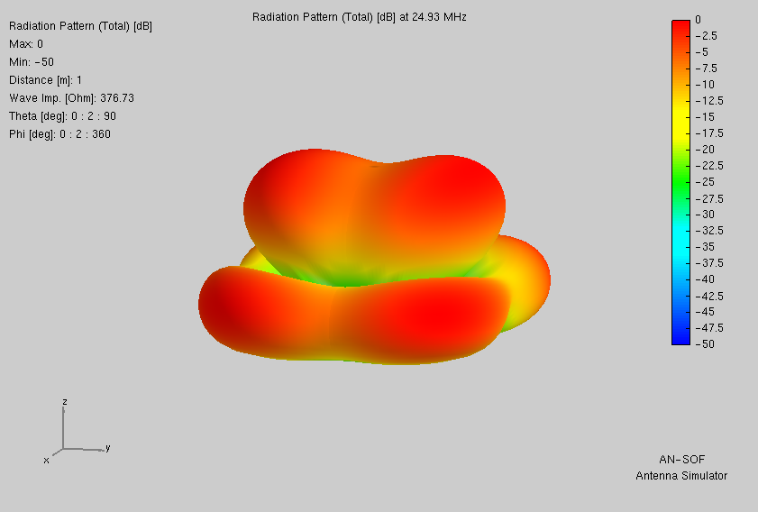
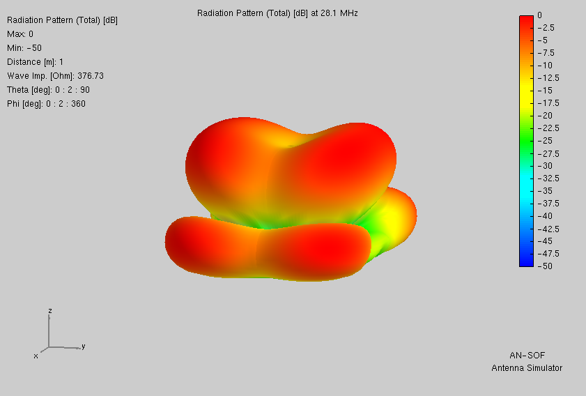
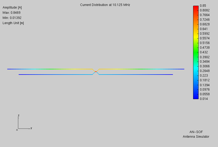
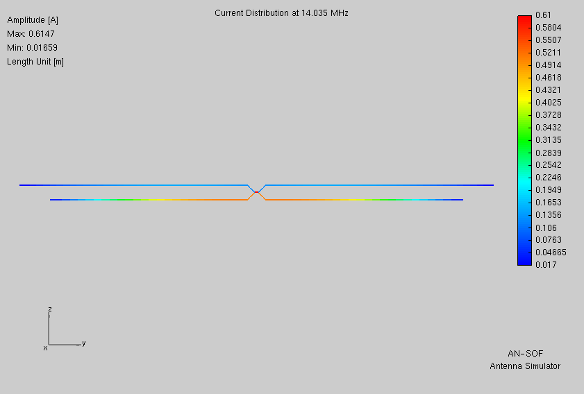
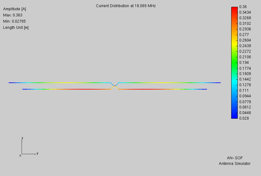
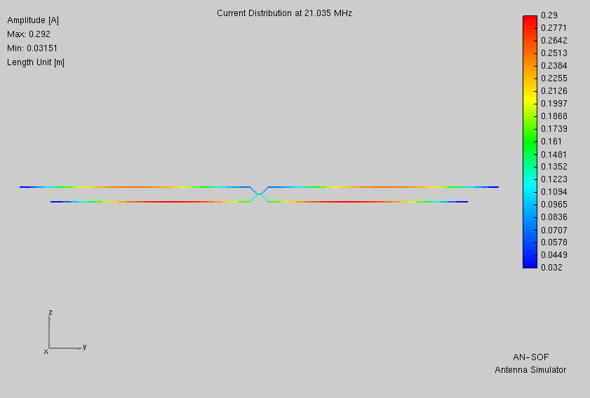
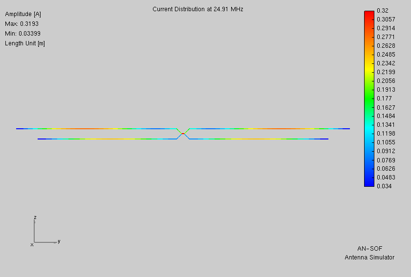
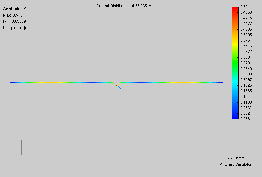
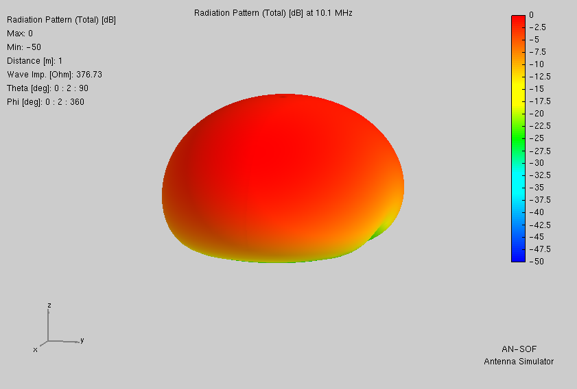
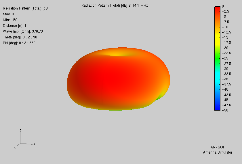
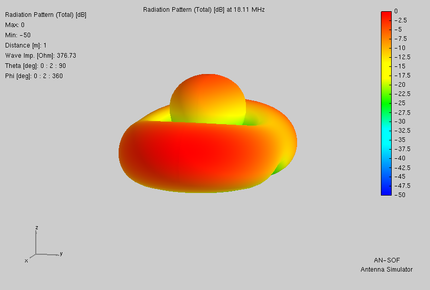
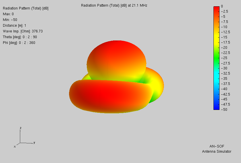
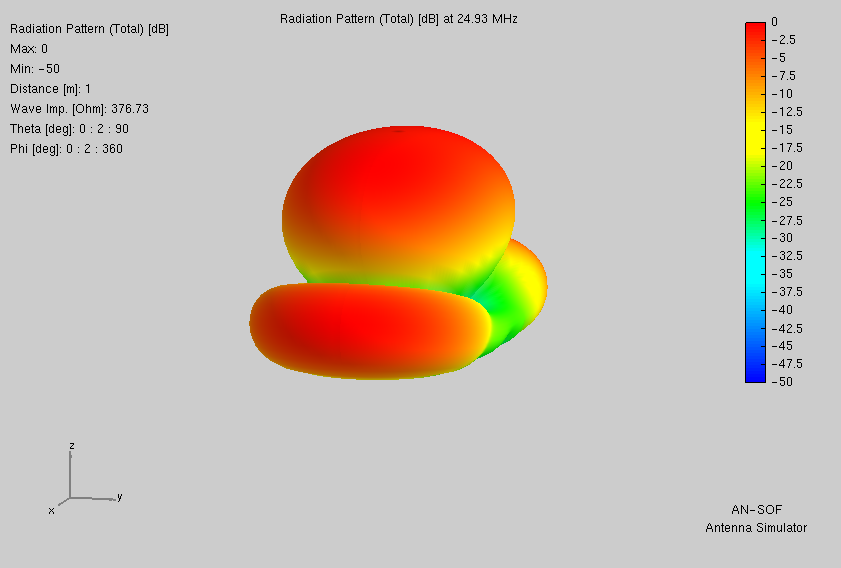
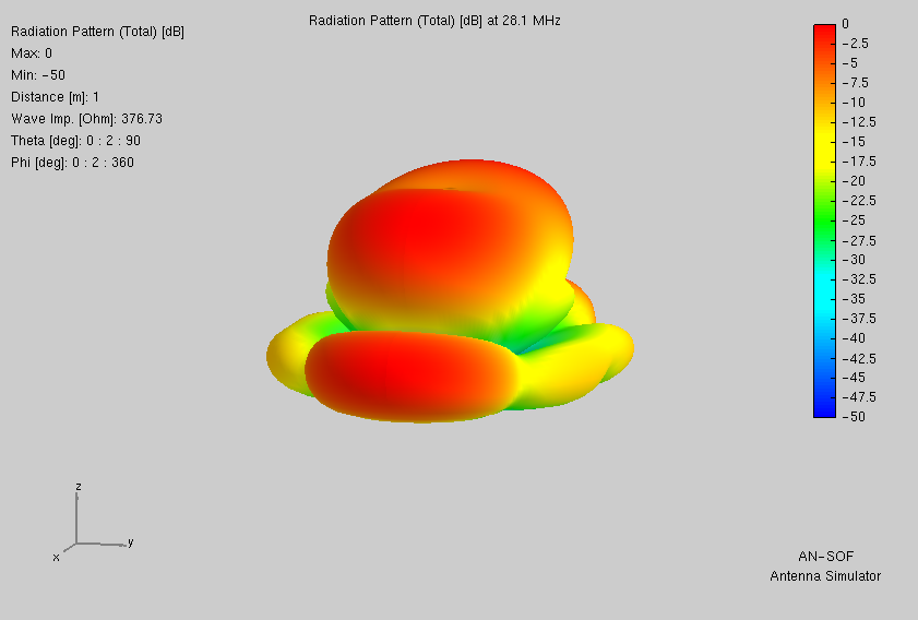
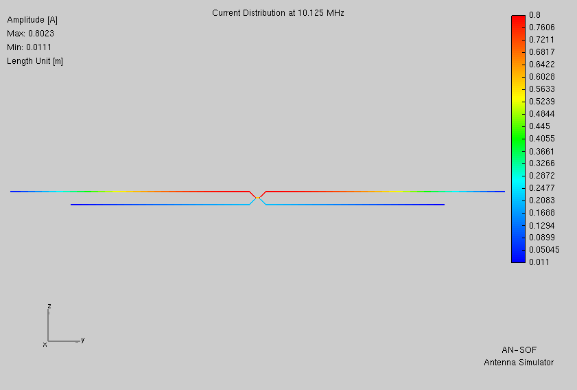
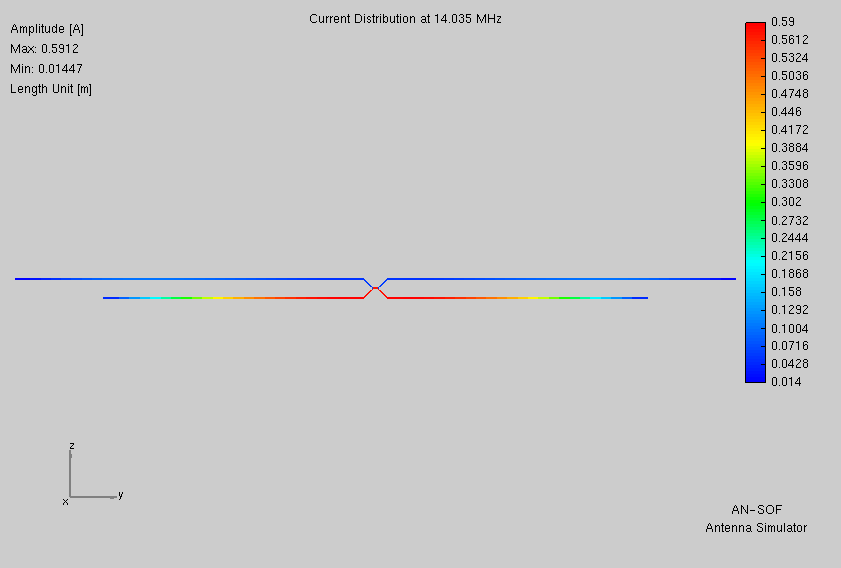
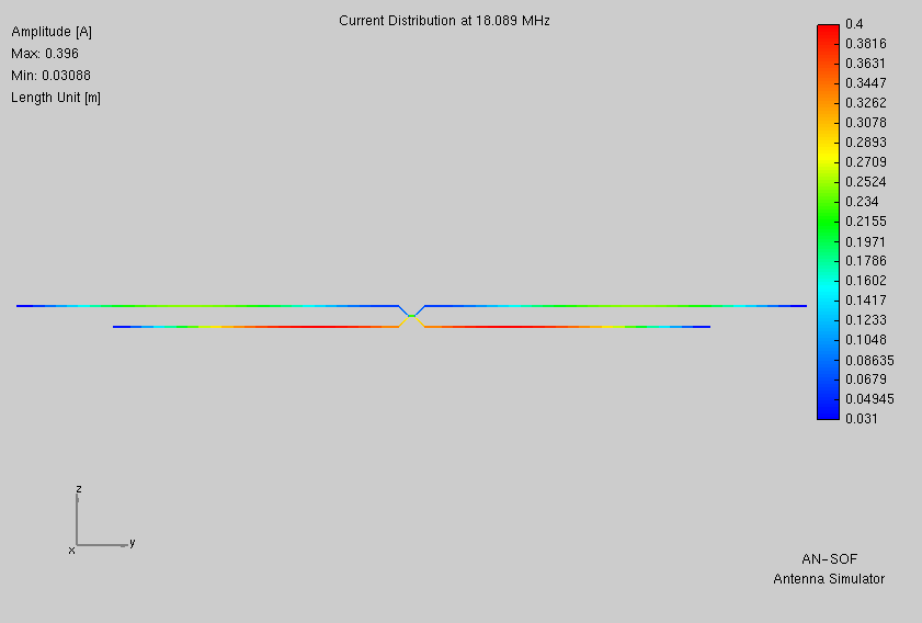
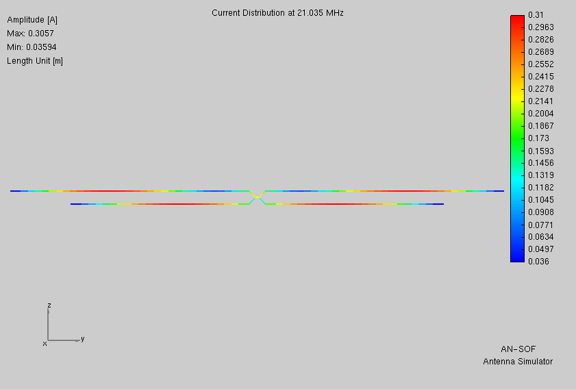
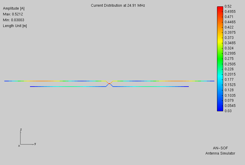
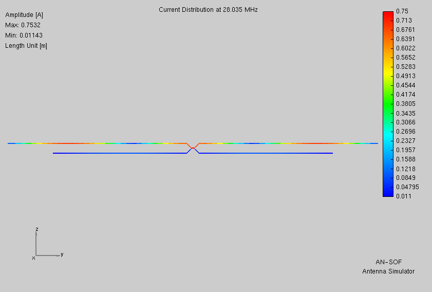
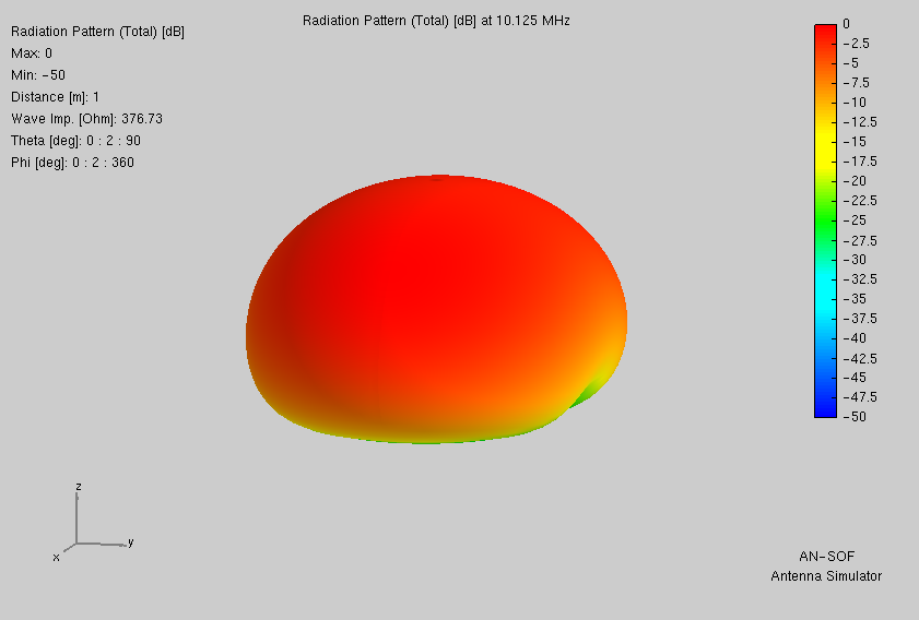
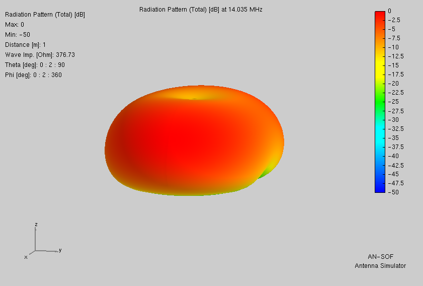
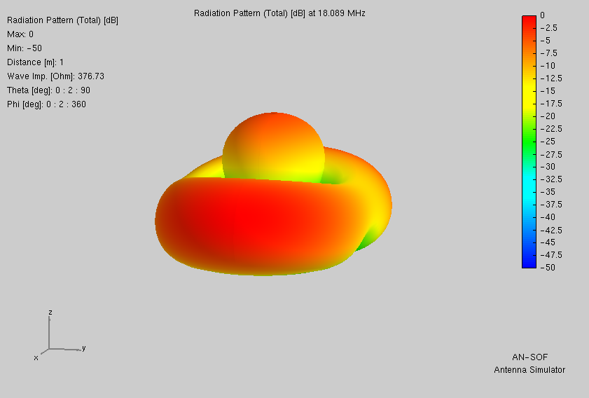
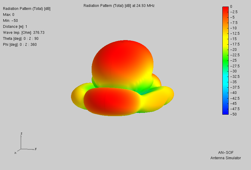
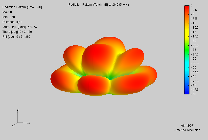
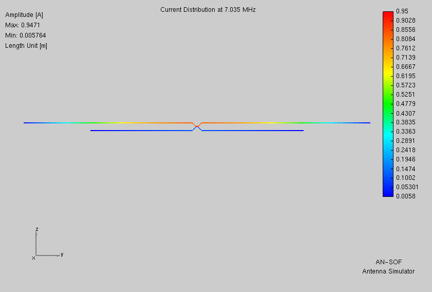
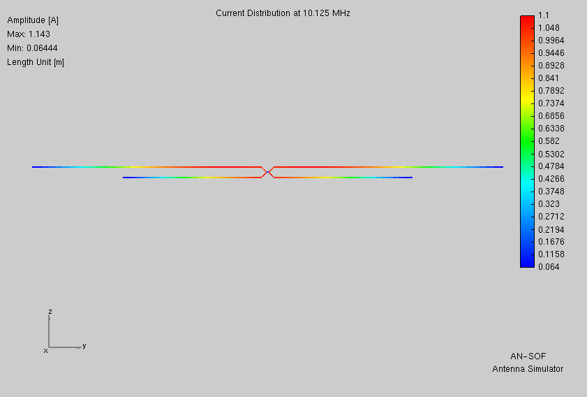
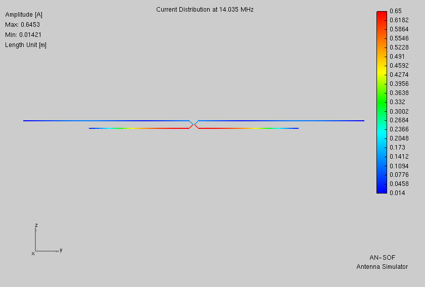
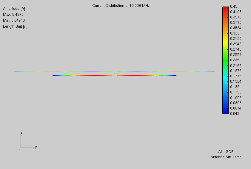
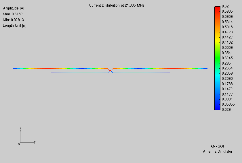
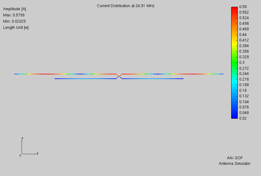
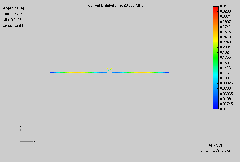
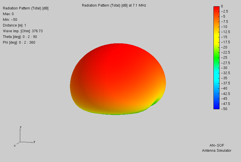
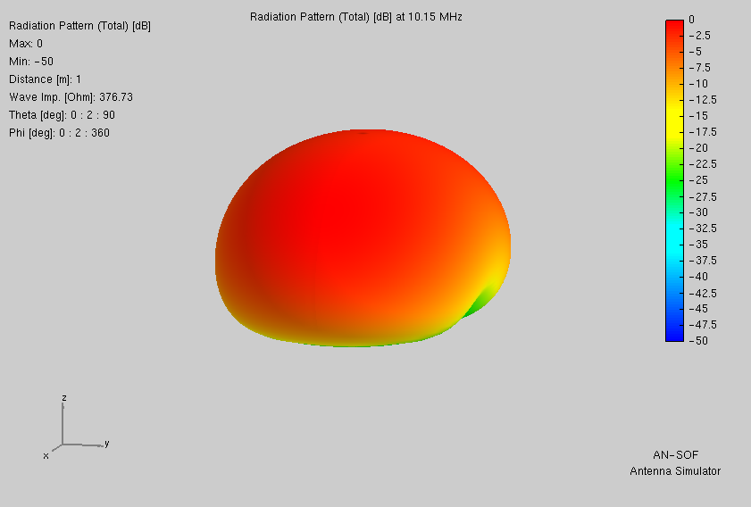
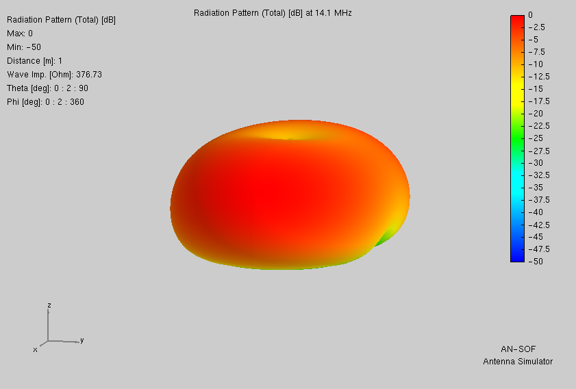
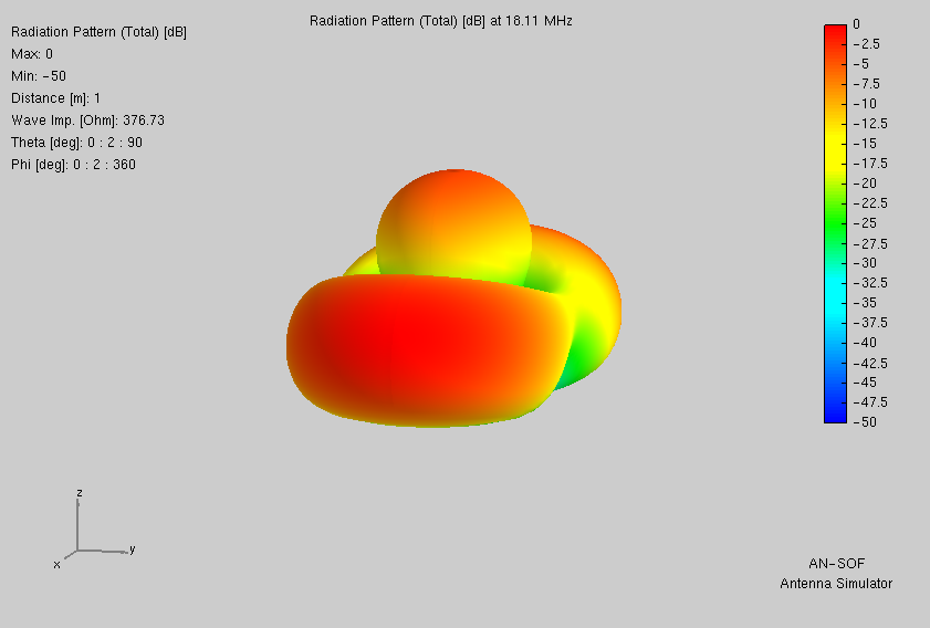
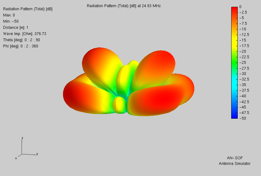
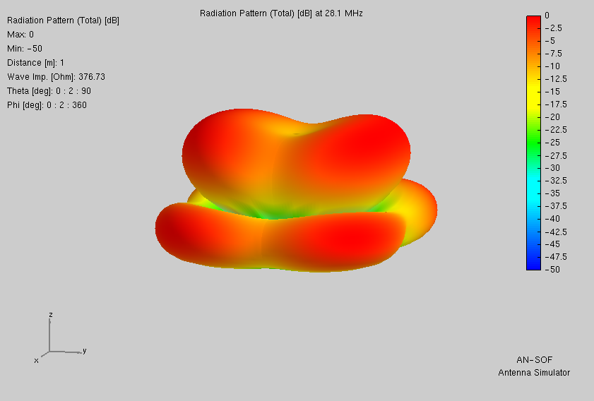
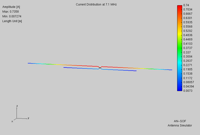
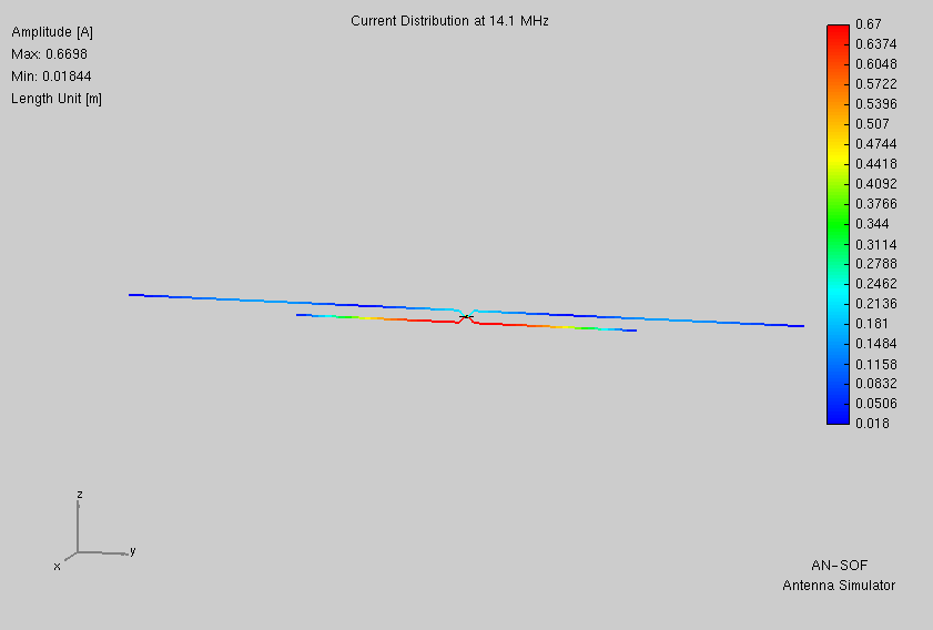
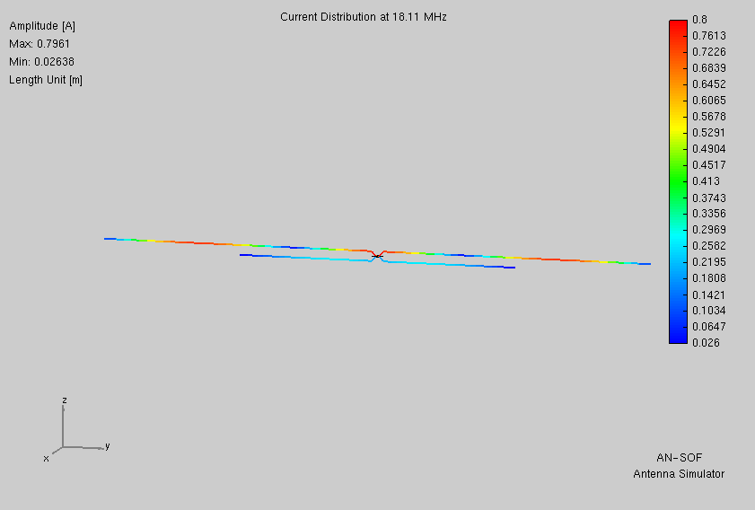
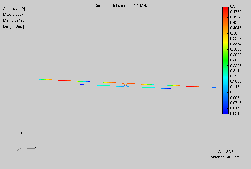
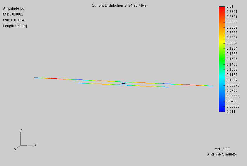
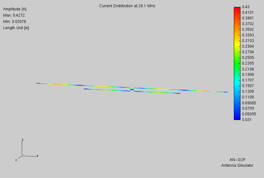
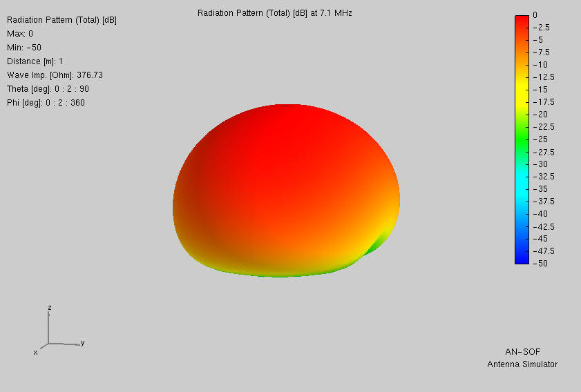
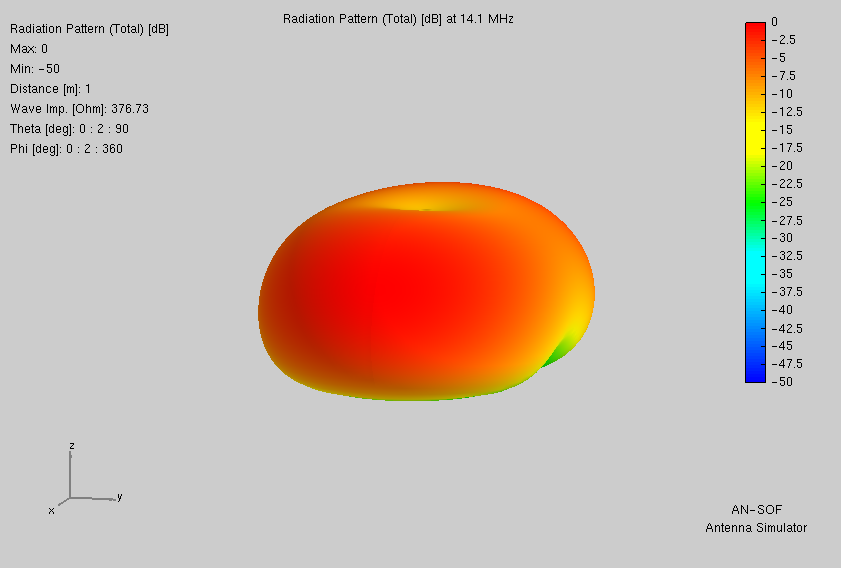
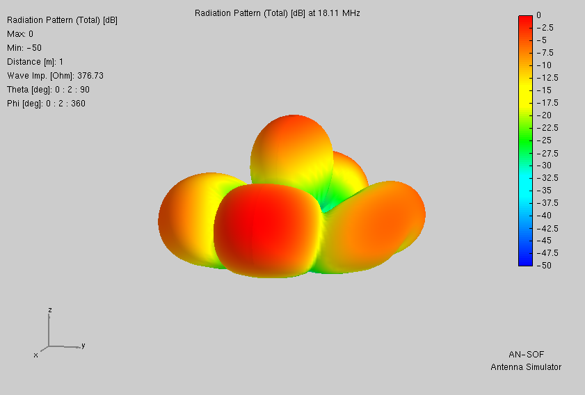
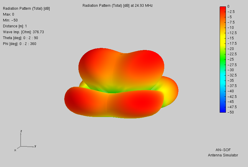
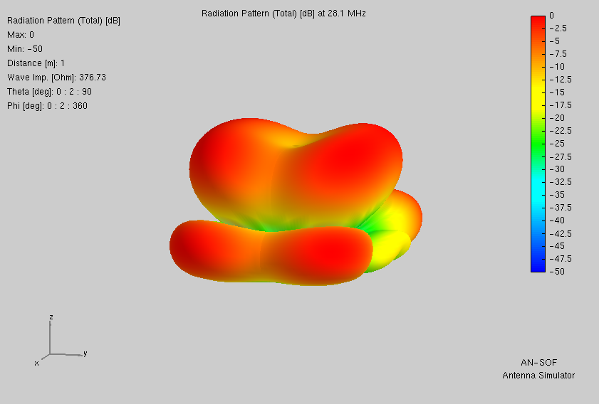
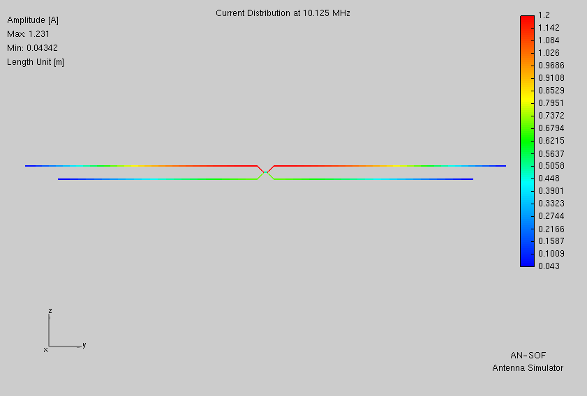
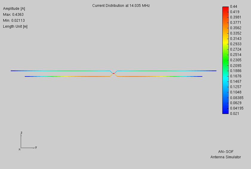
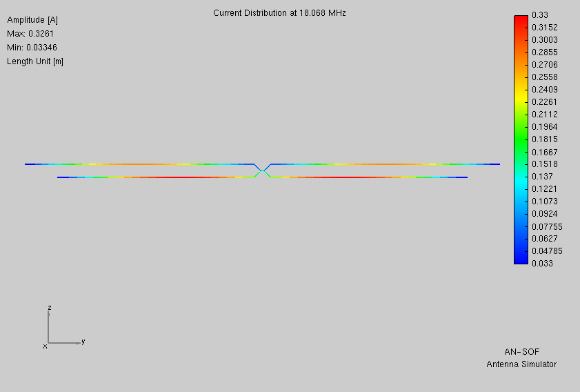
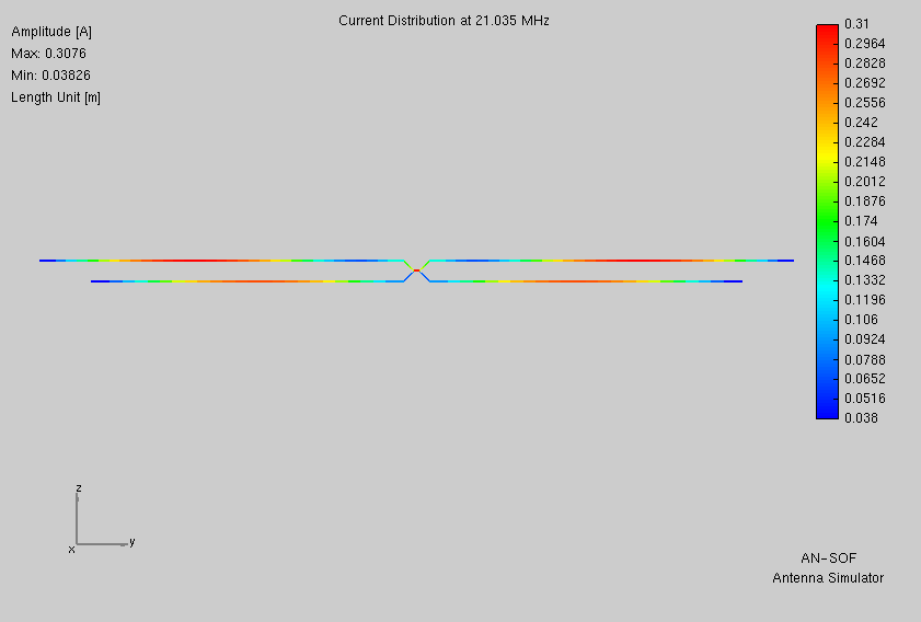
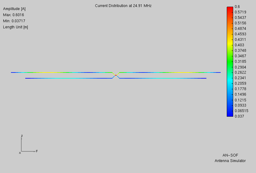
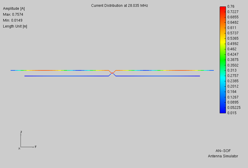
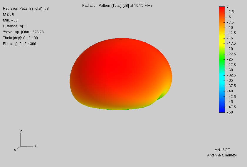
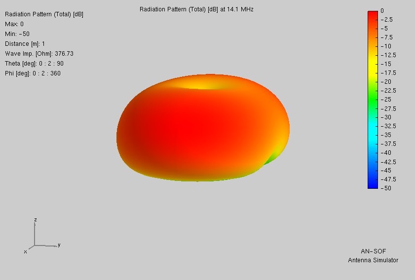
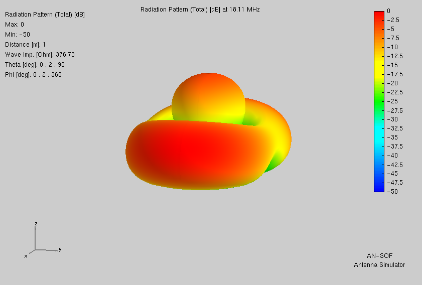
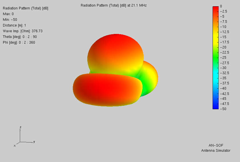
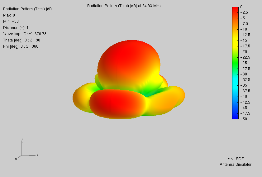
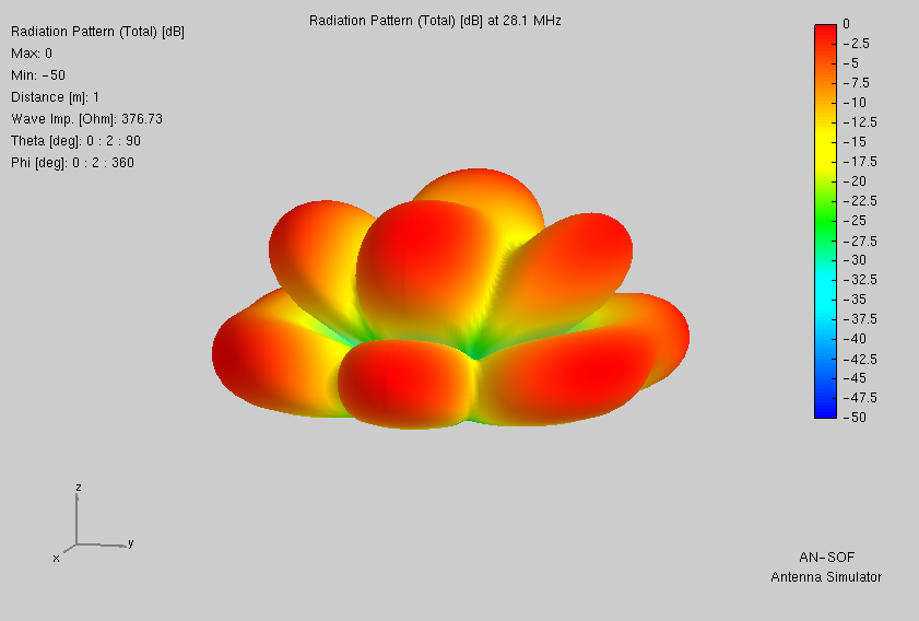
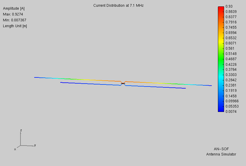
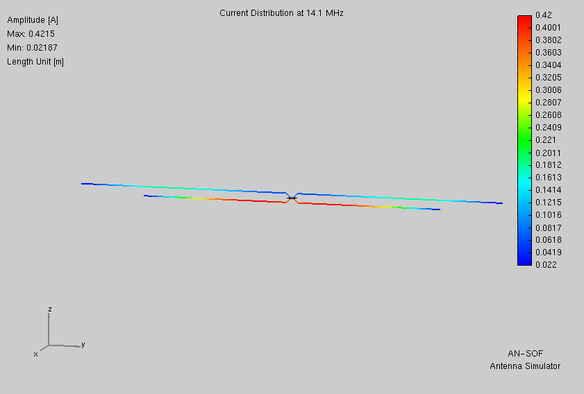
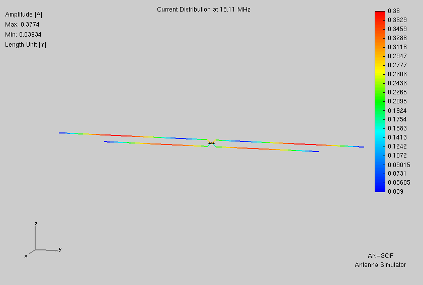
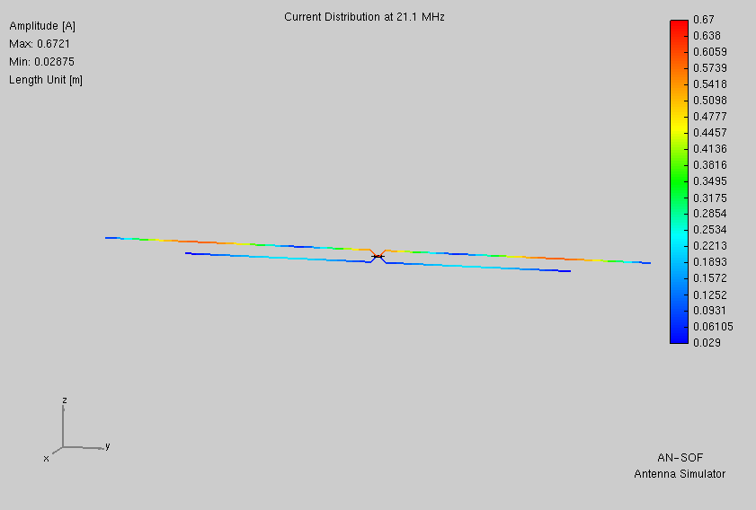
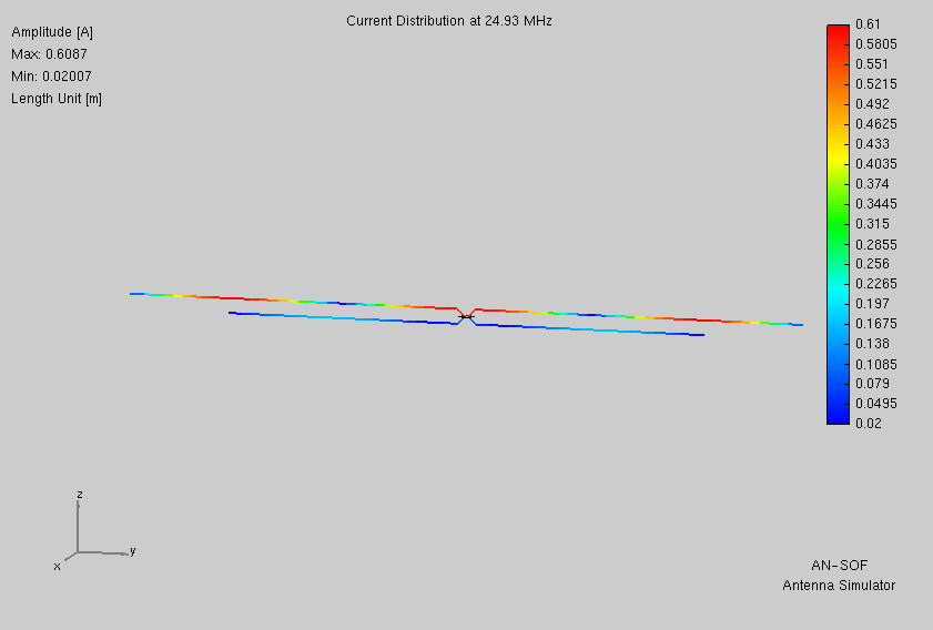
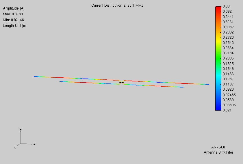
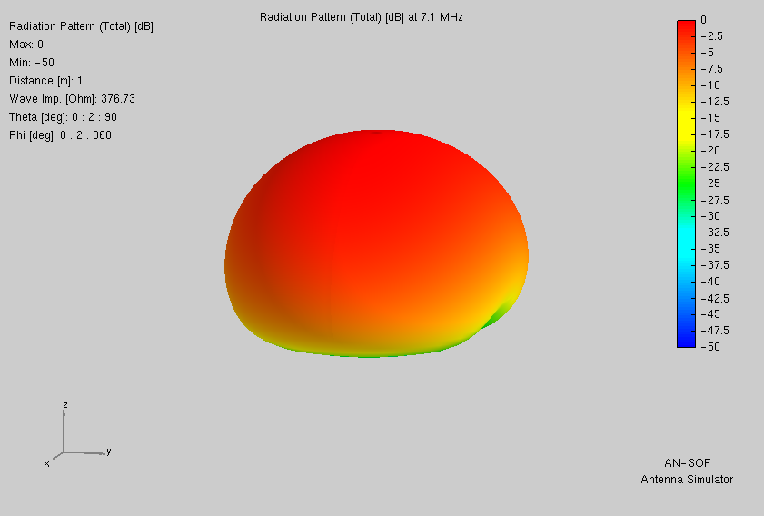
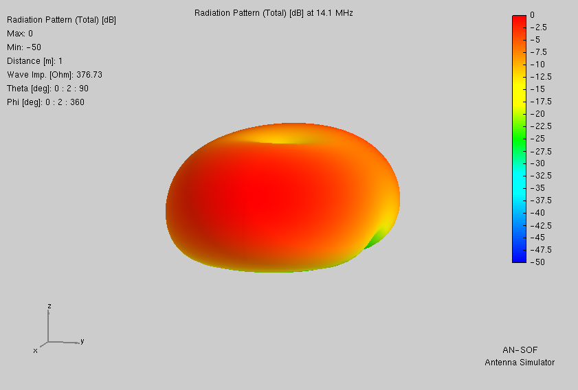
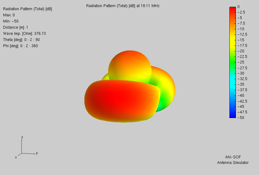
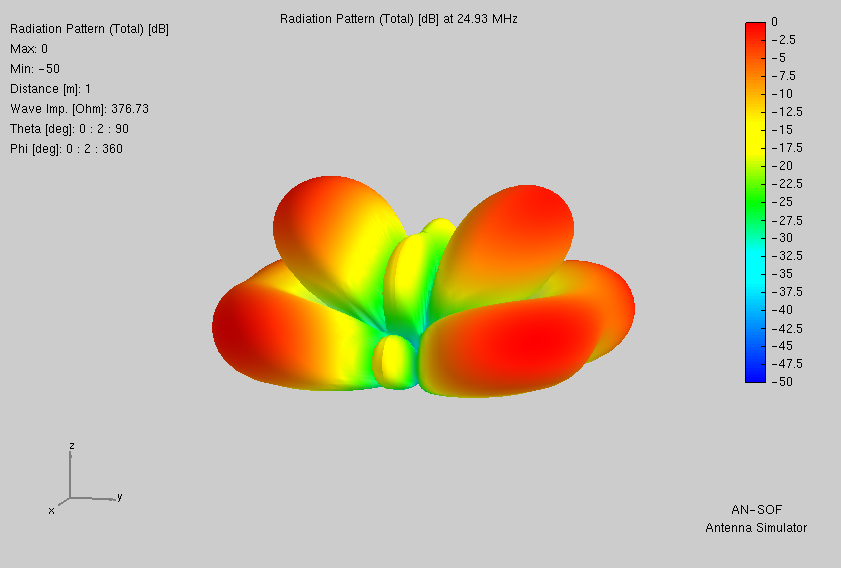
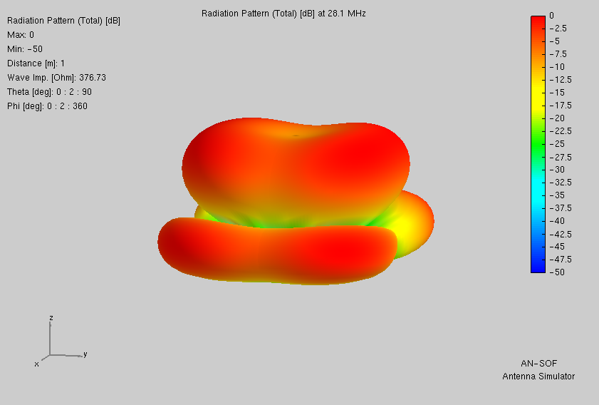
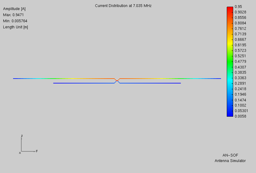
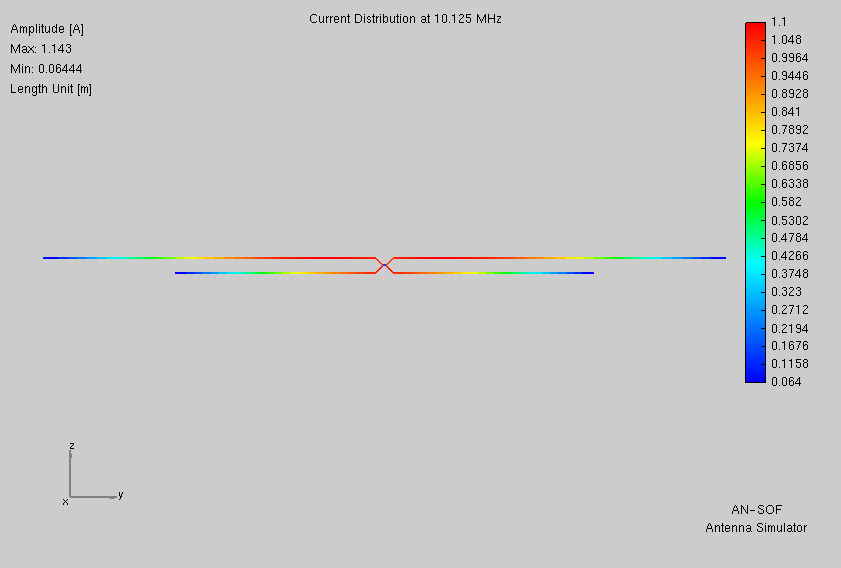
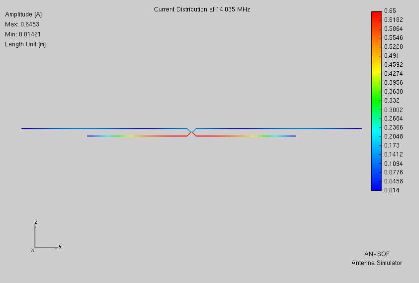
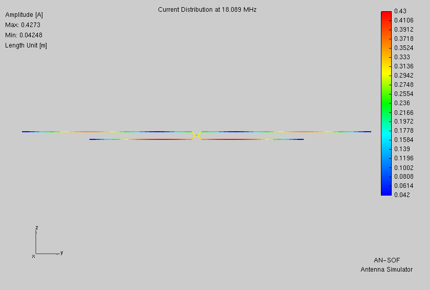
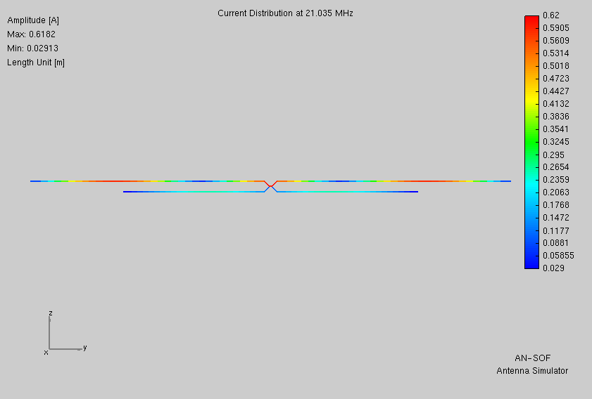
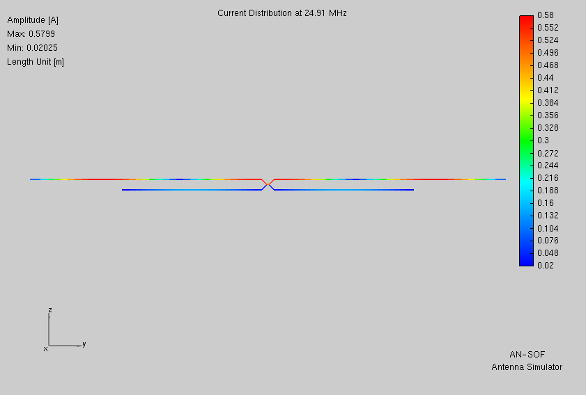
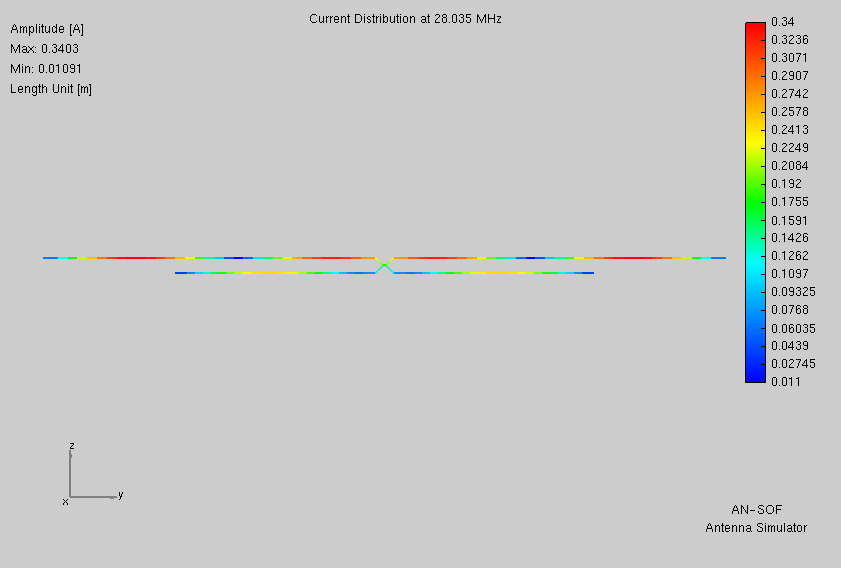
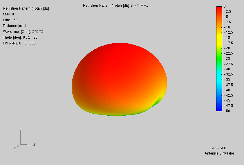
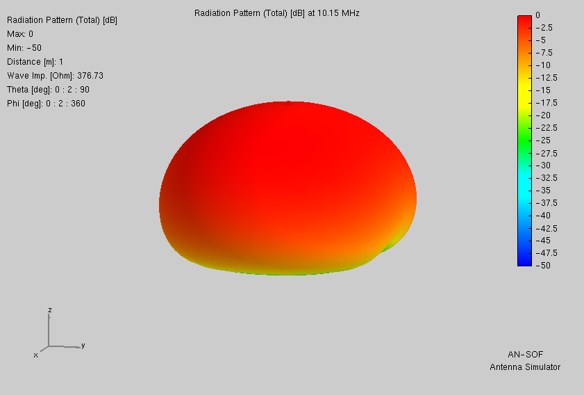
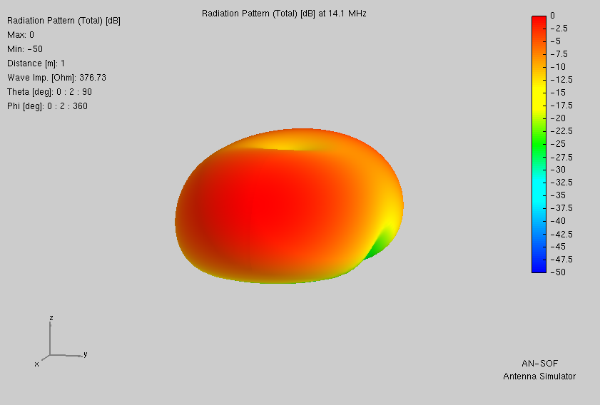
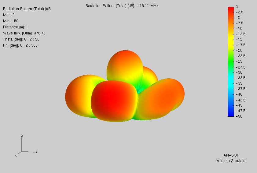
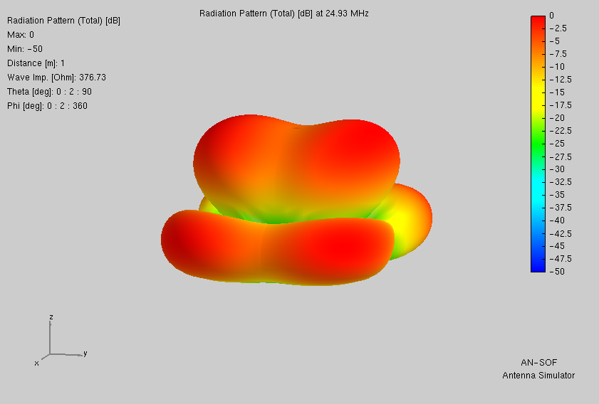
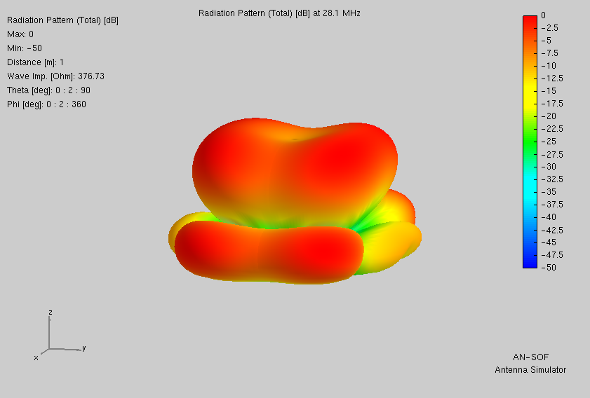
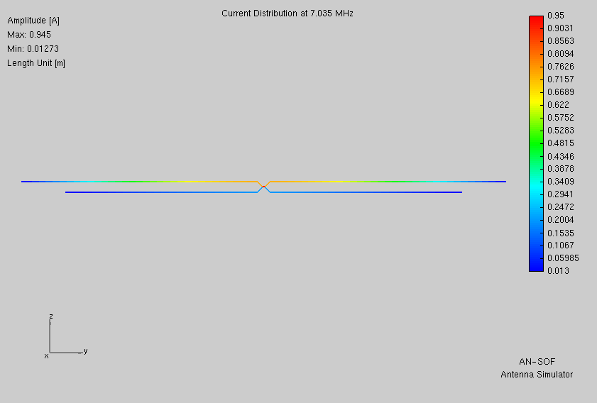
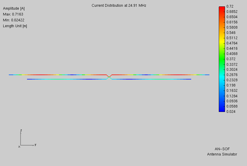
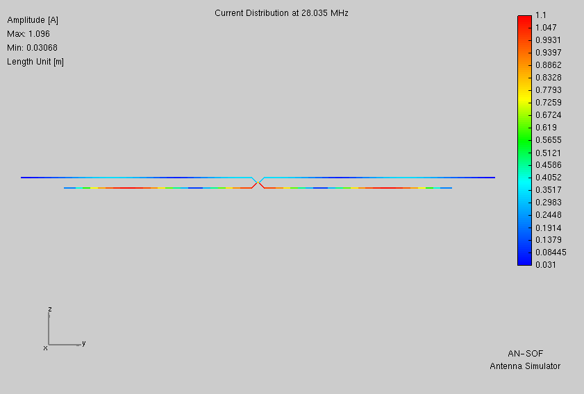
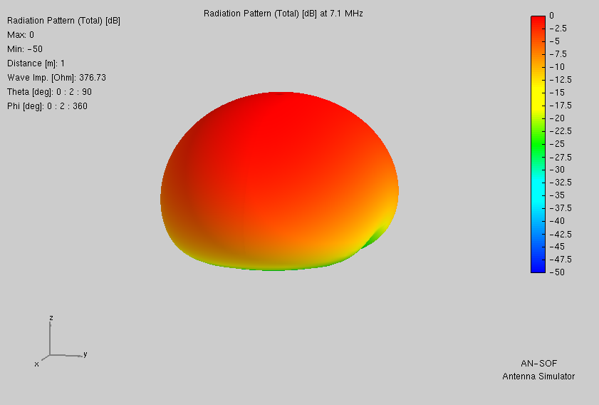
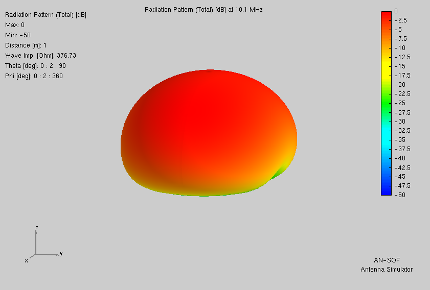
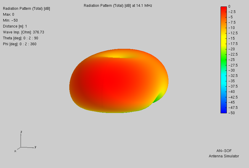
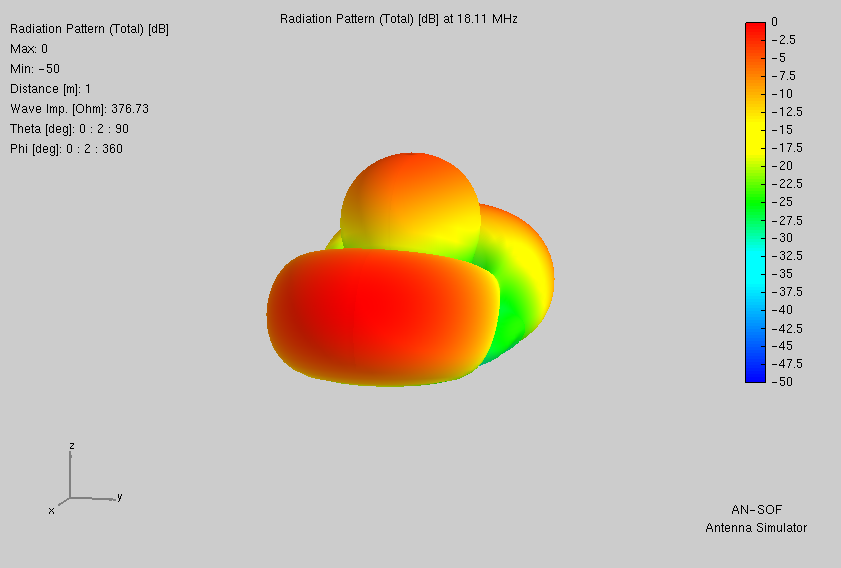
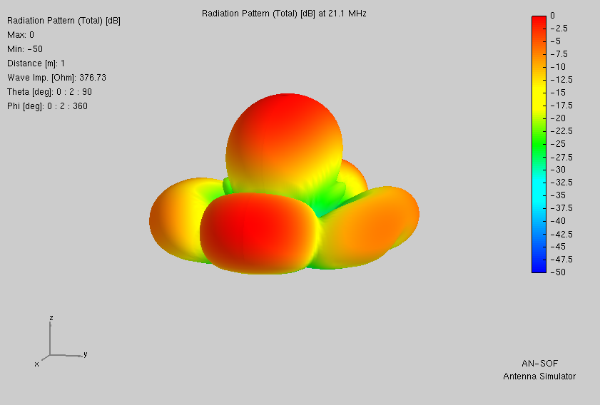
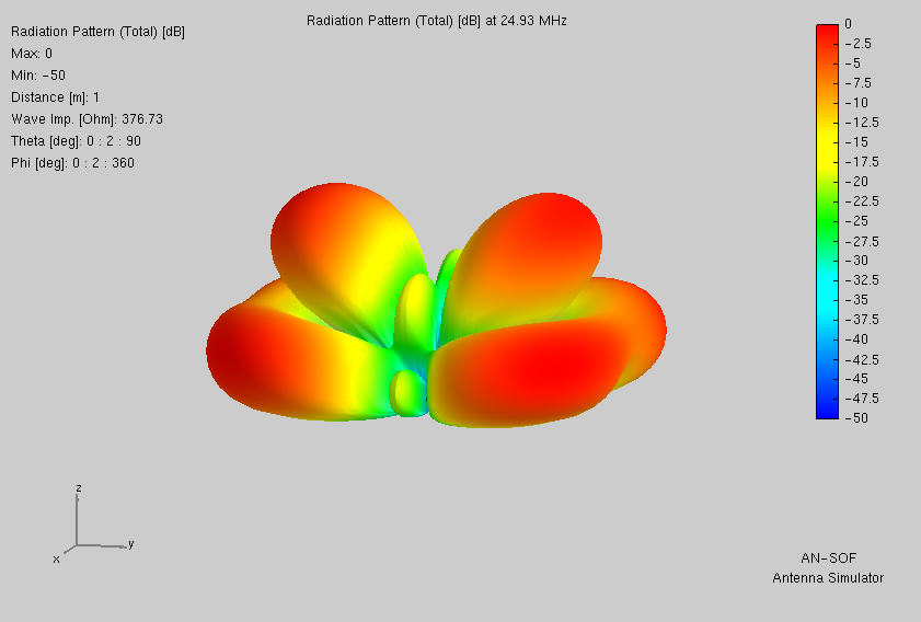
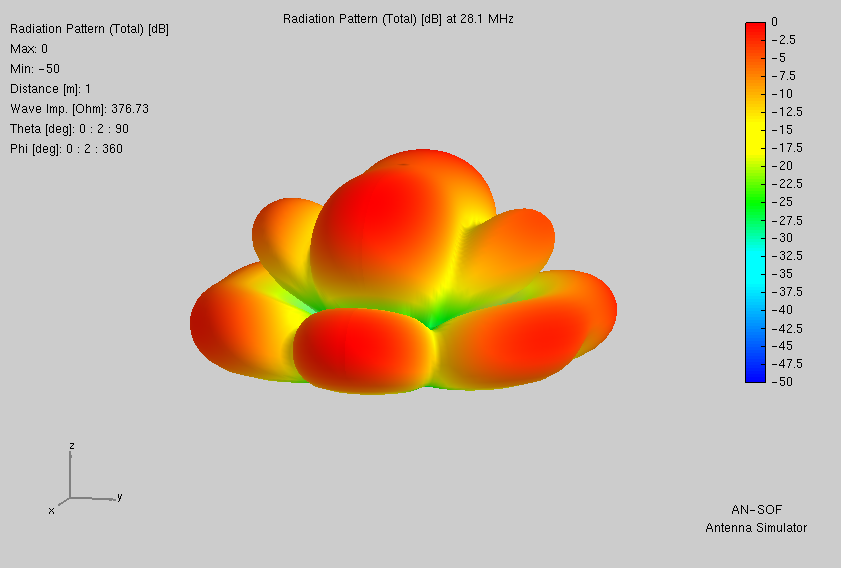
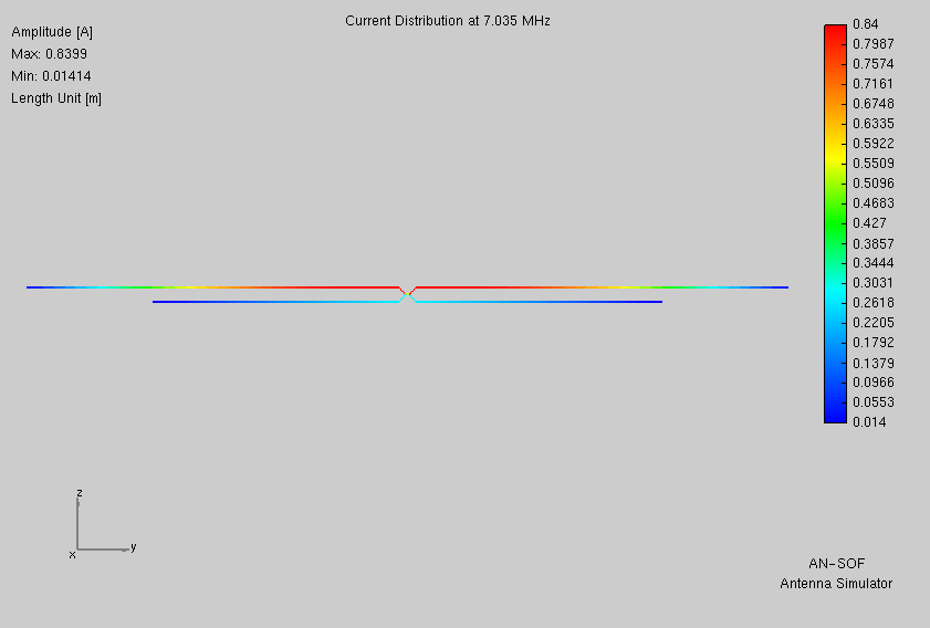
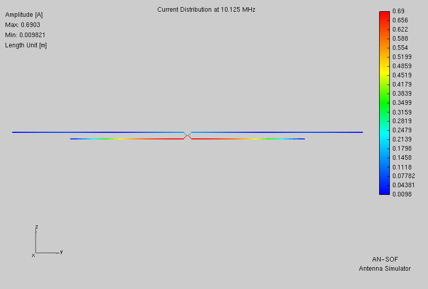
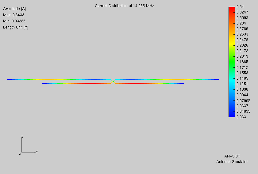
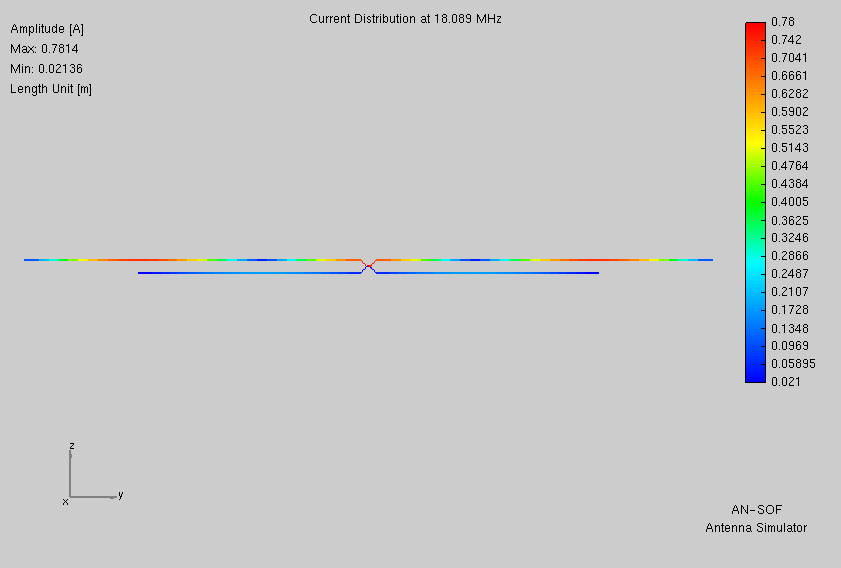
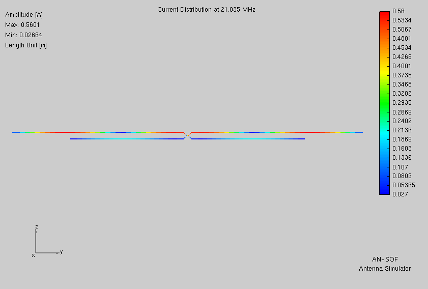
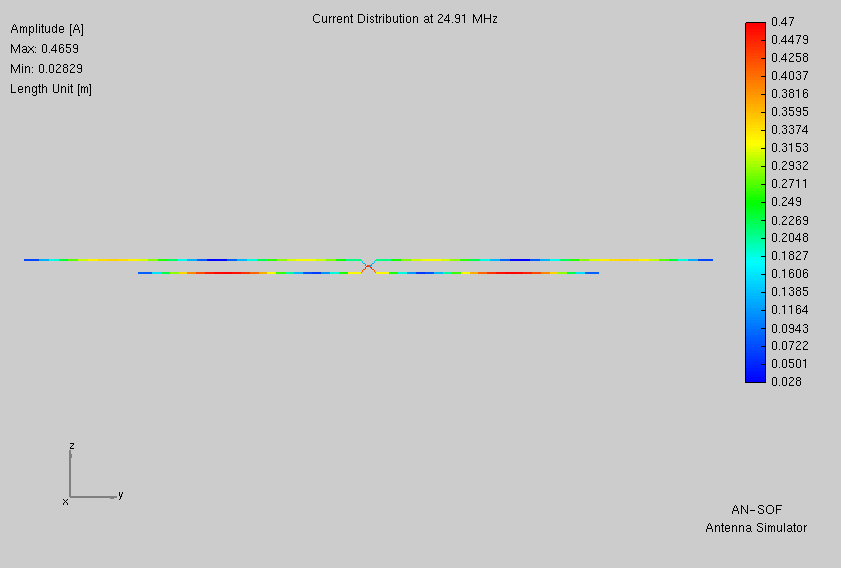
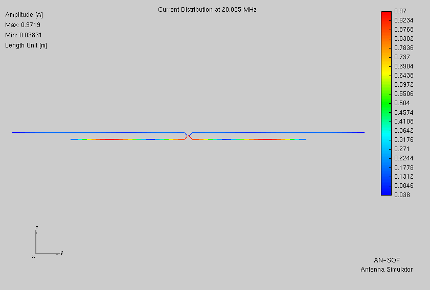
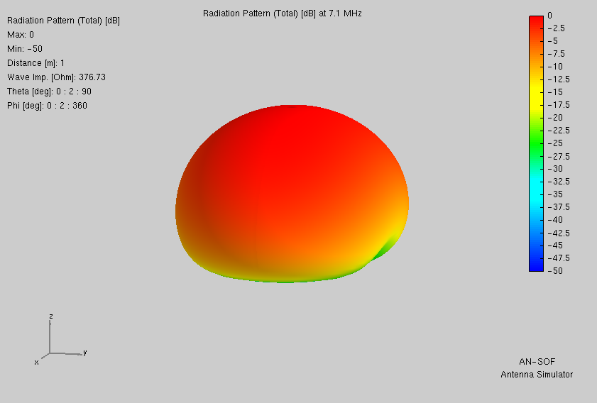
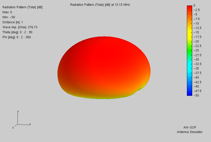
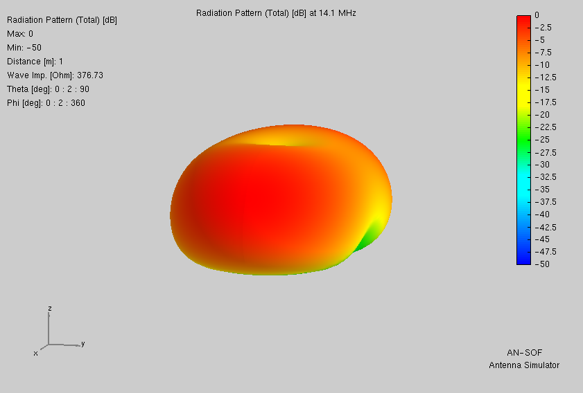
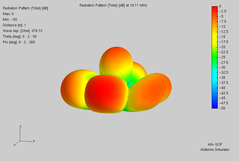
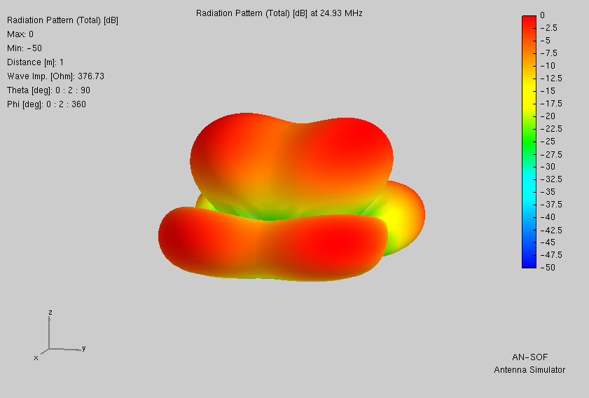
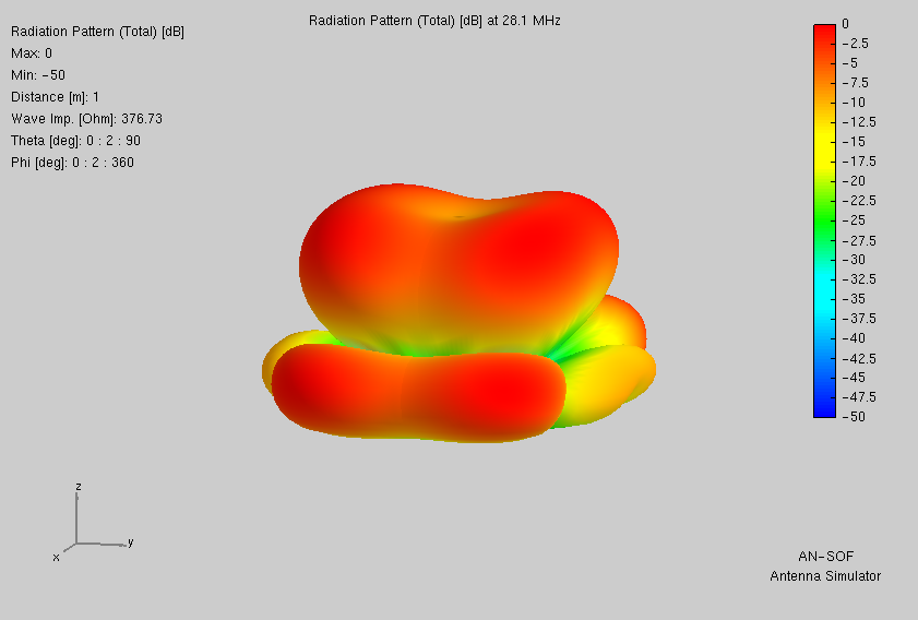
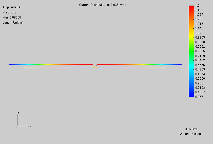
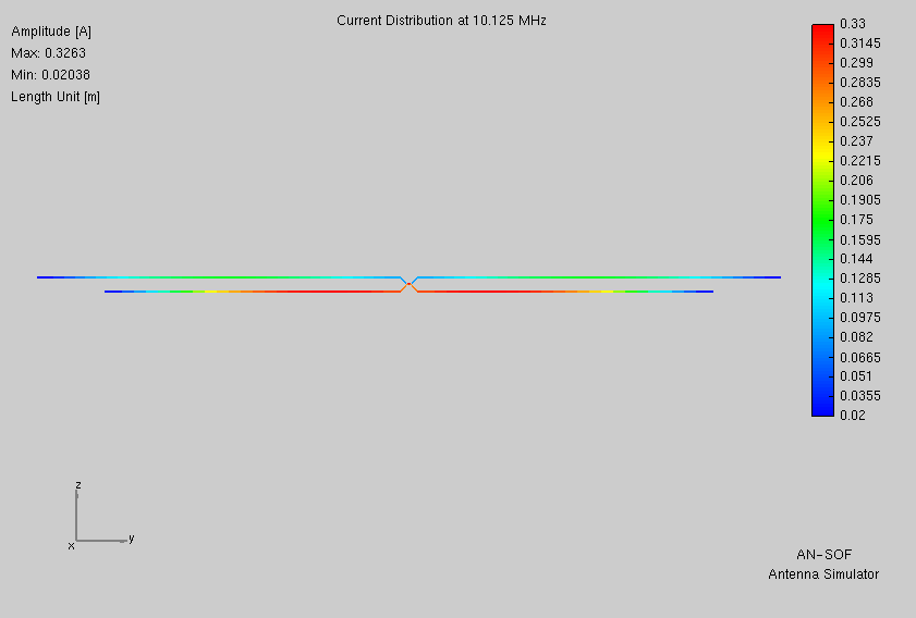
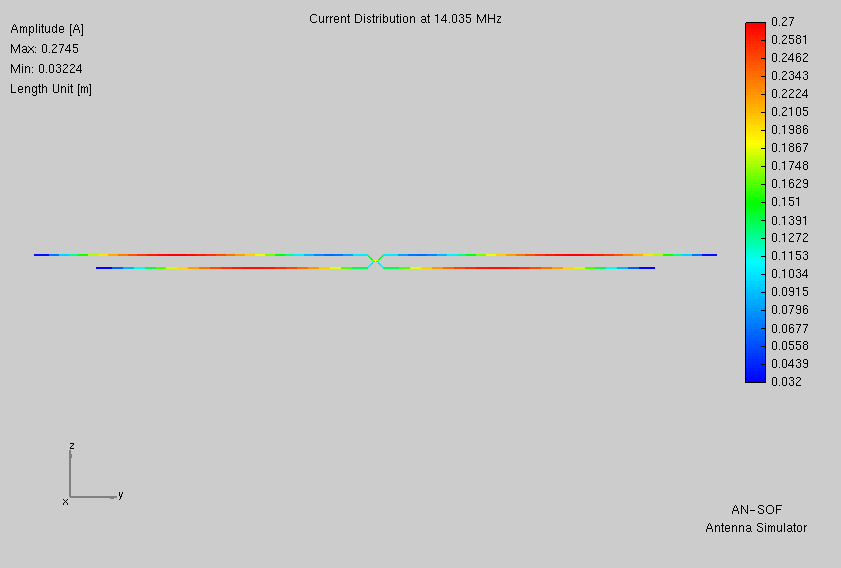
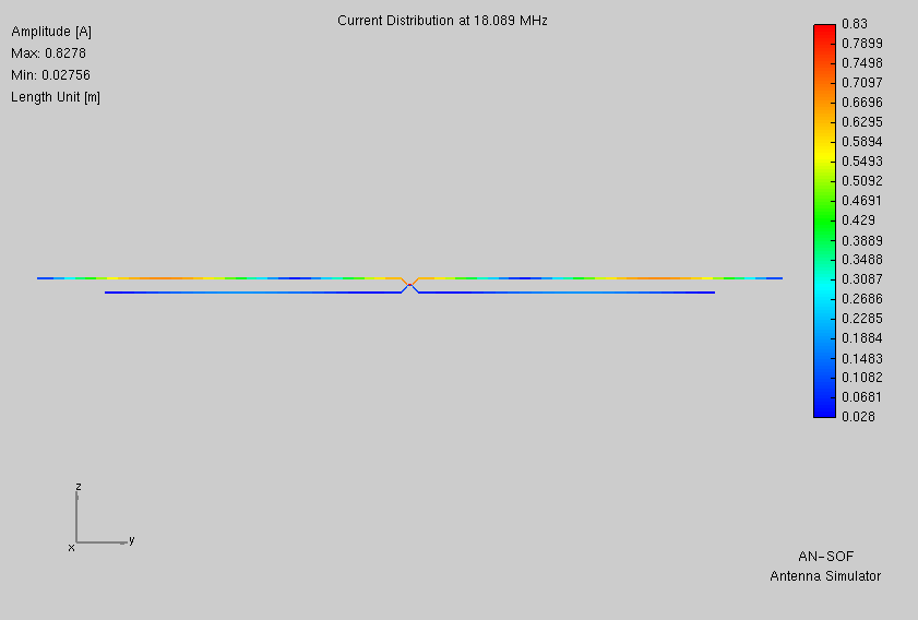
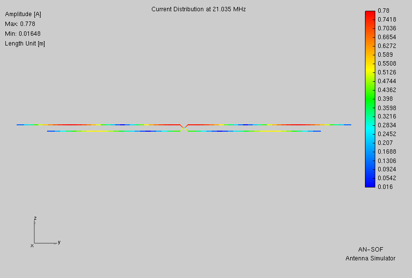
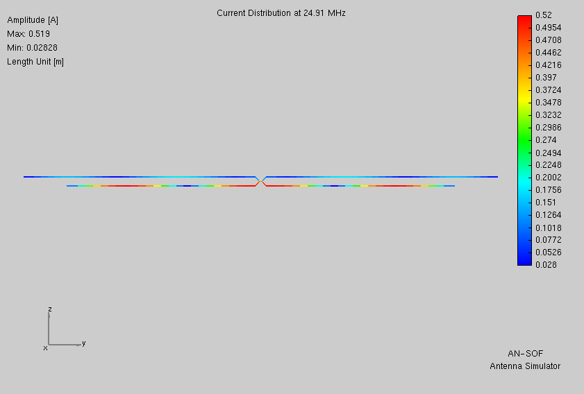
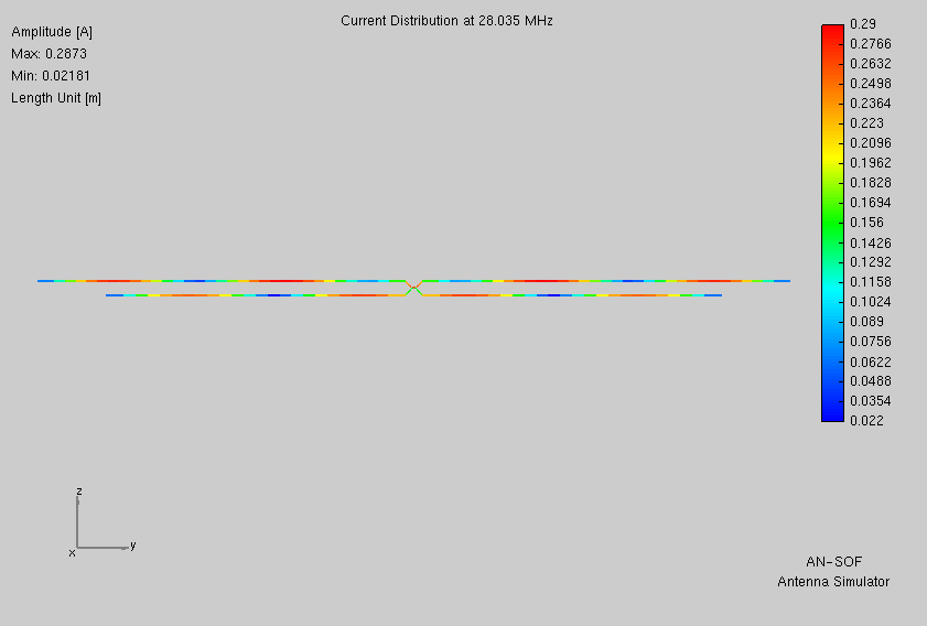
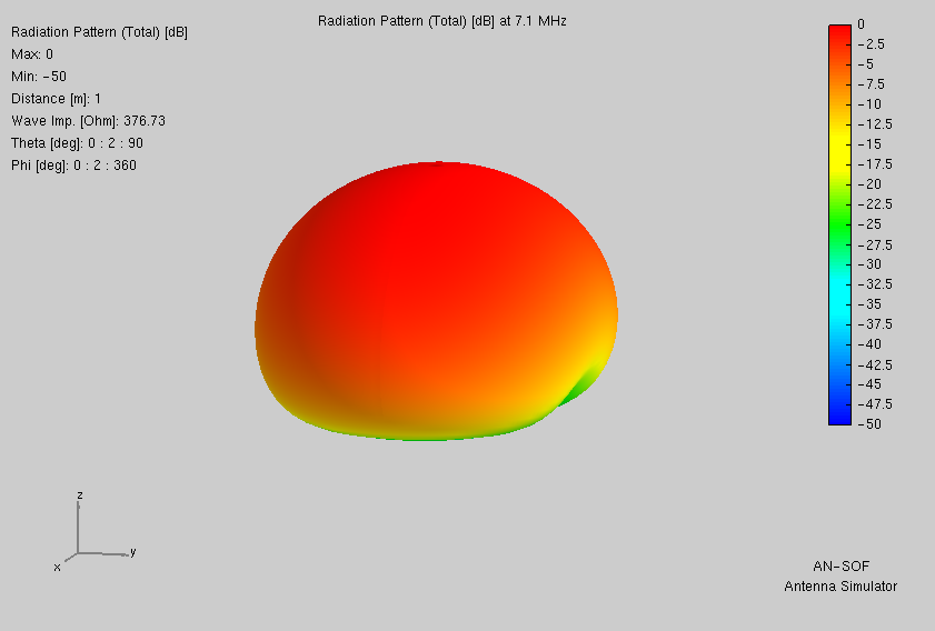
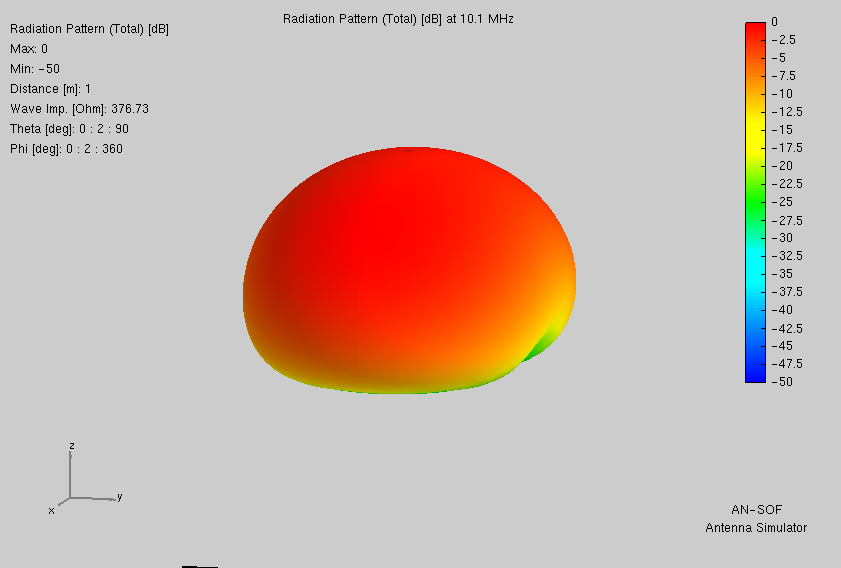
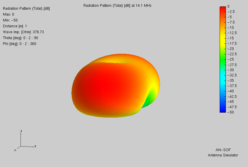
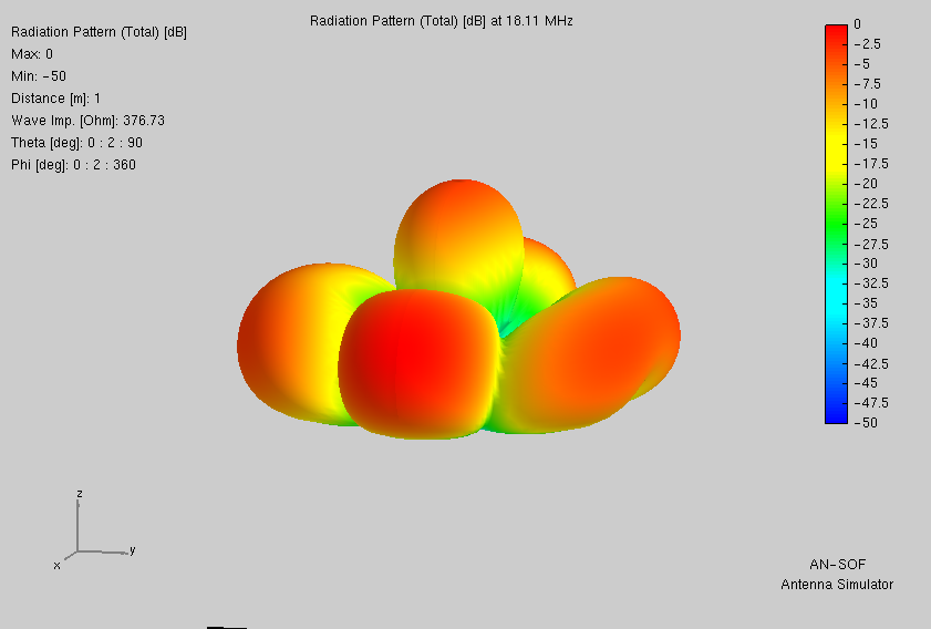
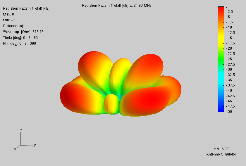
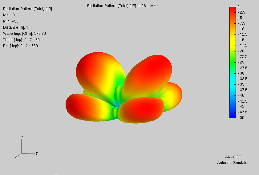
I then go on to obtain each antenna’s current distribution and radiation pattern for every band.
From these results I then choose particular models to build and test.
This page supplies modeling data for fifteen separate pairings of non-resonant wire lengths. Of those pairings modeled, this section lists only those showing promise according to AN-SOF.
Performance varies for each on each band. I group them here by those bands (WARC included) for which antenna current looks adequate. The sublists order by wire-pairing overall length (smallest at top). In parentheses list maximum antenna currents in Amperes per band. The alphabetical buttons are links.
Useable Bands: 30m—10m
Useable Bands: 40m—10m
Check marks in the above list indicate that design having been built and tested. If showing green (✔), then indeed the design proved out well.
If showing red (✔), results were less pleasing. One or more bands could not be matched. At least not by my LDG RT-100.
Feedline employed was a 15.24m (50 foot) length of 300Ω ladder line. Prior to each field test, that design’s software model was re-analyzed for compatiblity said feedline. The auto-tuner employed was my newly purchased LDG RT-100.
In theory, all these antennas ought to work. That some do not may be due to the predicted analog tuning solutions falling between the step values achievable by relay-switched components.
On repeated occasions where no match was obtained, I observed this disappointing occurrence. My Daiwa cross-needle SWR meter showed plural intermittent readings of at least low-ish SWR. Instances where I would have been satisfied for it to stop. Yet stop it did not. It passed those by until in the end giving up. And upon giving up, the final SWR was very much higher than several of those which it passed by.
Why, having found nothing better, cannot the RT-100 at least return to the best match obtained, even if not wholly satisfactory? Were it to do that, then I could just turn it off, depending upon the latching relay to hold that value while next employing the rig’s built-in auto-tuner to fine-tune the rest of the way. Exactly as I have done on rare occasion in times past, then employing an MFJ 16010 at the coax cable’s far end. Alas and alack.
These parameters apply to all antennas modeled below.
Z-match components: In-range on bands 30m—10m.
| Values Required | Min | Max |
|---|---|---|
| L | 0.75μH | 5.37μH |
| C | 17.0pF | 89.6pF |
Z-match components: untunable on 20m; in-range on other bands 30m—10m.
| Values Required | Min | Max |
|---|---|---|
| L | 0.97μH | 5.00μH |
| C | 14.1pF | 75.8pF |
Z-match components: Out-of-range on 14m. In-range on other bands 30m—10m.
| Values Required | Min | Max |
|---|---|---|
| L | 0.24μH | 7.30μH |
| C | 24.2pF | 116pF |
Z-match components: 20m untunable; In-range for other bands 40m—10m.
| Values Required | Min | Max |
|---|---|---|
| L | 0.69μH | 5.32μH |
| C | 23.0pF | 174pF |
Z-match components: 20m untunable; In-range for other bands 40m—10m.
| Values Required | Min | Max |
|---|---|---|
| L | 0.69μH | 5.32μH |
| C | 23.0pF | 174pF |
Z-match components: In-range for bands 30m—12m. Out-of-range for 10m.
| Values Required | Min | Max |
|---|---|---|
| L | 0.52μH | 5.01μH |
| C | 8.90pF | 120pF |
Z-match components: In-range for bands 30m—10m.
| Values Required | Min | Max |
|---|---|---|
| L | 0.325μH | 4.341μH |
| C | 13.5pF | 113pF |
Z-match components: In-range for 40m—10m.
| Values Required | Min | Max |
|---|---|---|
| L | 0.32μH | 4.34μH |
| C | 13.4pF | 113pF |
Z-match components: 30m untunable; In-range for other bands 40m—10m.
| Values Required | Min | Max |
|---|---|---|
| L | 0.47μH | 6.80μH |
| C | 11.4pF | 99.3pF |
Z-match components: In-range for bands 30m—10m.
| Values Required | Min | Max |
|---|---|---|
| L | 0.27μH | 4.08μH |
| C | 11.7pF | 86.6pF |
Z-match components: 30m untunable; In-range for other bands 40m—10m.
| Values Required | Min | Max |
|---|---|---|
| L | 0.88μH | 5.32μH |
| C | 15.0pF | 169pF |
Z-match components: Untunable on 30m; In-range for otherbands 40m—10m.
| Values Required | Min | Max |
|---|---|---|
| L | 0.22μH | 7.30μH |
| C | 2.42pF | 116pF |
Z-match components: In-range for bands 40m—10m.
| Values Required | Min | Max |
|---|---|---|
| L | 0.50μH | 5.48μH |
| C | 9.4pF | 164pF |
Z-match components: In-range for bands 40m—10m.
| Values Required | Min | Max |
|---|---|---|
| L | 0.54μH | 6.74μH |
| C | 4.31pF | 120pF |
Z-match components: In-range for bands 40m—10m.
| Values Required | Min | Max |
|---|---|---|
| L | 0.92μH | 6.60μH |
| C | 20.4pF | 159pF |
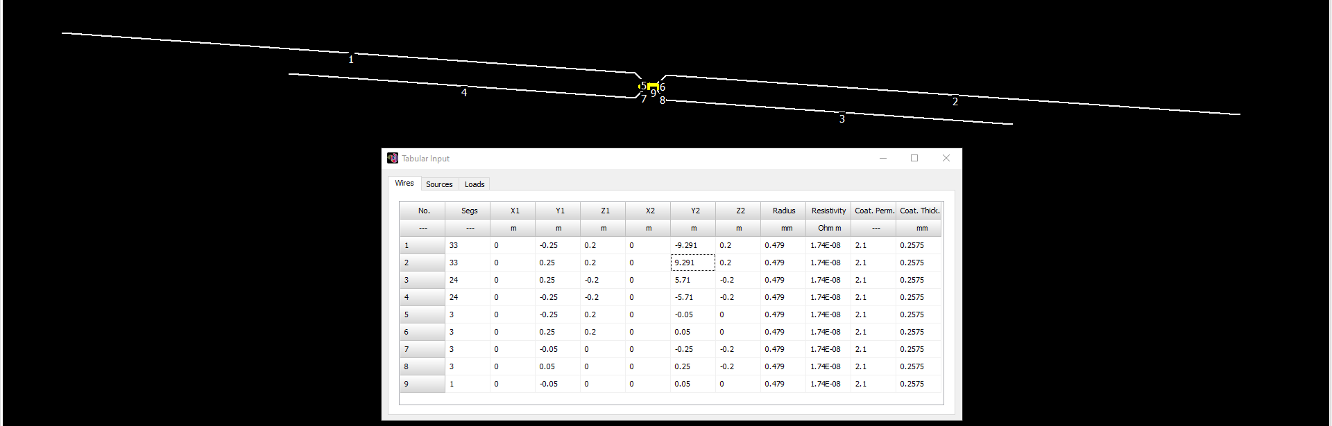
Wishing to reduce overall length by half, I thought to try out the center-fed antenna above as an end-fed by deleting its -Y half: wires 1, 4, 5, and 7. Results were dismal results as shown below. Nor did alternate balun ratios help.
Z-match components: 40m—12m untunable; in-range only on 10m.
Network configuration: CC for 20m—12m; excessive pF required on 40m & 30m; first LC then CL on 10m.
Latin for “Let the moocher beware”. I composed this for me, and employed it with glee. I share it here with you for free, but offered without even so much as the smell of a dead warranty (or wheriot, as the case may be). Whatsoever disasters of cosmic proportion as may result from the use of this information, any and all culpability rests wholly and solely with the user.
My contact email and postal address are on QRZ.com for call sign KY8D